Method and apparatus for a low cost, high speed, and compact nanometer precision motion stage using friction drive and flexure hinge

a technology of friction drive and flexure hinge, which is applied in the direction of hoisting equipment, gearing, instruments, etc., can solve the problems of high cost, complicated sub-systems, and high cost of 6 axis motion control stages incorporating these sub-systems

Inactive Publication Date: 2005-01-11
PANASONIC HEALTHCARE HLDG CO LTD
View PDF5 Cites 10 Cited by
  • Summary
  • Abstract
  • Description
  • Claims
  • Application Information

AI Technical Summary

Benefits of technology

The present invention provides a friction drive for providing precision motion. In an exemplary embodiment, the friction drive comprises a drive shaft and a follower in frictional contact. The drive shaft is in frictional contact at a contact area for imparting a thrust to the f

Problems solved by technology

A 6-axis motion control stage incorporating these sub-systems, however, can be very expensive.
These sub-systems are also complicated, having a high part count that can cause reliability problems.
Yet another problem with these systems is that they typically require speed reduction devices, such as gear sets or lead screws to create sufficient torque for many precision motion applications.
Such speed reduction devices incorporate play or looseness of fit that can cause backlash and dead spots in the motion system, as well as, lateral forces that reduce the precision of the stage motion.
Thus, the friction drive motor

Method used


Image

  • Method and apparatus for a low cost, high speed, and compact nanometer precision motion stage using friction drive and flexure hinge
  • Method and apparatus for a low cost, high speed, and compact nanometer precision motion stage using friction drive and flexure hinge
  • Method and apparatus for a low cost, high speed, and compact nanometer precision motion stage using friction drive and flexure hinge

Examples


Embodiment Construction

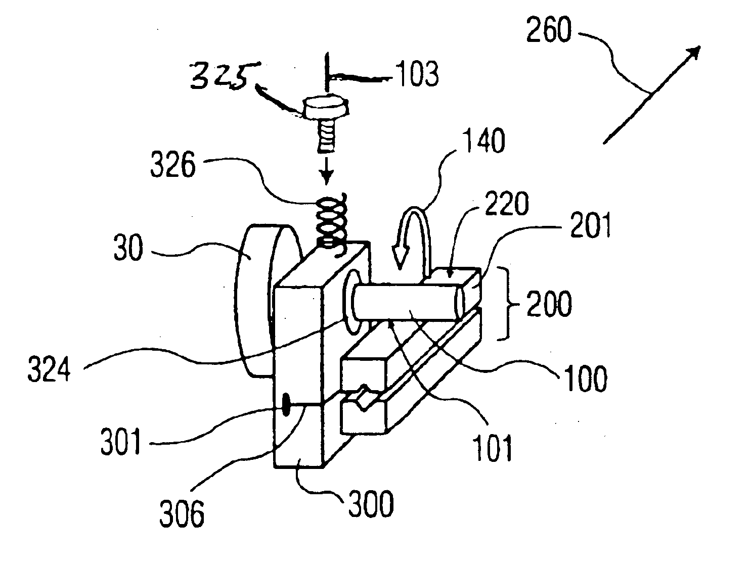
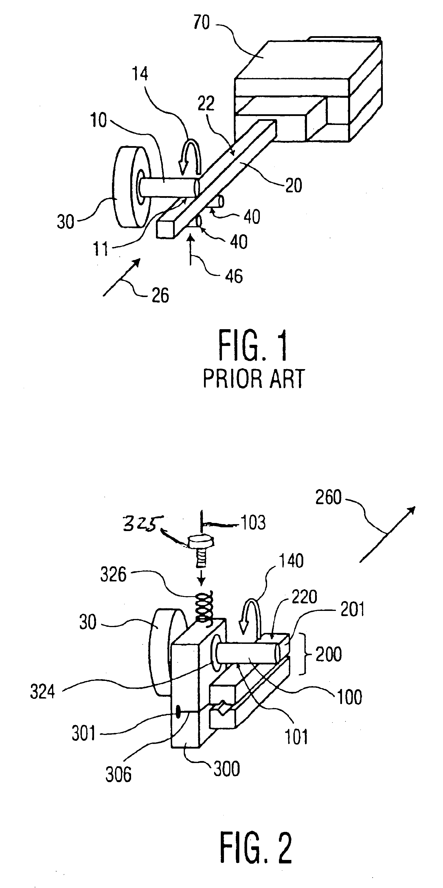
Referring now to the drawing, in which like reference numbers refer to like elements throughout, FIG. 1 illustrates a friction drive system according to the prior art. A motor 30 is used to rotate a drive shaft 10 in a direction of rotation 14. A follower 20 has a friction surface 22, a portion of which is in contact with a contact area 11 of shaft 10. Backup rollers 40 apply a pre-load force 46 to follower 20 urging friction surface 22 toward shaft 10. Drive shaft 10 is constrained in a fixed position relative to follower 20, such as by a bearing (not shown). Accordingly, drive shaft 10 acts as a transmission member, generating a frictional force or thrust 26, by rotation of drive shaft 10 which is forced against friction surface 22. Thrust 26 acts on frictional surface 22 of follower 20 to provide motion to follower 20. Thrust 26 is proportional to pre-load force 46, and the motion of follower 20 is proportional to the angular displacement of shaft 10. A linear guide 70 controls t...


PUM


Abstract

A friction drive including a drive shaft that is in rotational motion and in frictional contact with a follower at a contact area. The drive shaft transfers a thrust at the contact area. The follower receives the thrust and provides motion in response to the thrust. A flexure hinge couples the drive shaft to the follower with a constant force while restraining movement of the contact area in the direction of the thrust.

Description

TECHNICAL FIELDThis invention relates to generally to a precision motion system, and more particularly to a method and apparatus for providing a low cost, high speed, and compact precision motion stage having nanometer-range resolution using a friction drive with a flexure hinge.BACKGROUND OF THE INVENTIONPrecision motion systems with resolutions in a range down to ten nanometers are required in many manufacturing applications, including assembly and alignment of optical transmission and processing equipment. Typically, precision motion is provided by a combination of a DC or AC servo motor, a high precision feedback encoder, and a high precision linear bearing or guide. A 6-axis motion control stage incorporating these sub-systems, however, can be very expensive. These sub-systems are also complicated, having a high part count that can cause reliability problems. Yet another problem with these systems is that they typically require speed reduction devices, such as gear sets or lead...

Claims


Application Information

Patent Timeline
IPC IPC(8): G02B7/02H01L41/09G02B21/26H02N2/00
CPCG02B7/023H02N2/126H02N2/123
Inventor OHARA, TETSUO
Owner PANASONIC HEALTHCARE HLDG CO LTD
Why Eureka
Try Eureka