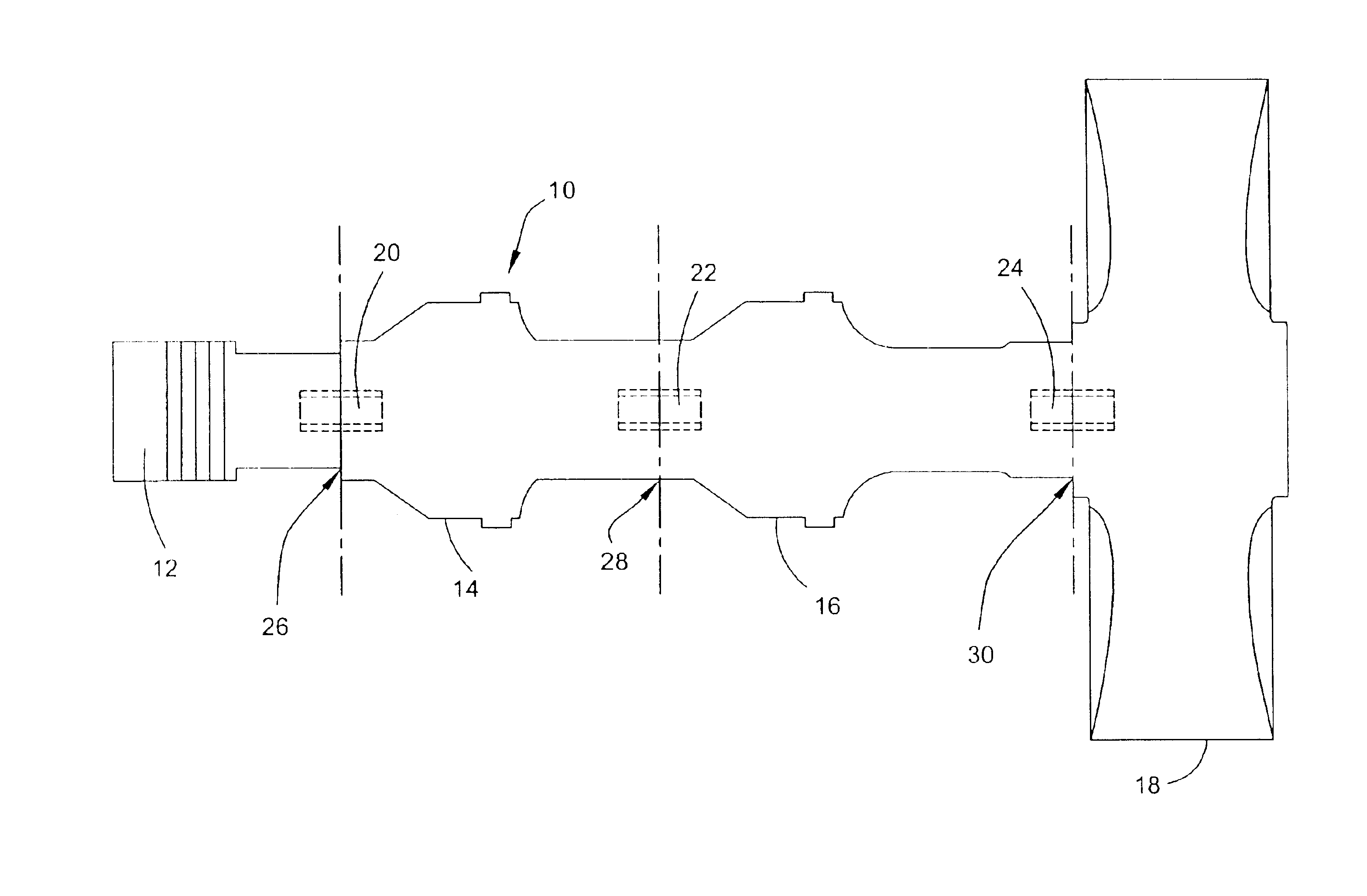
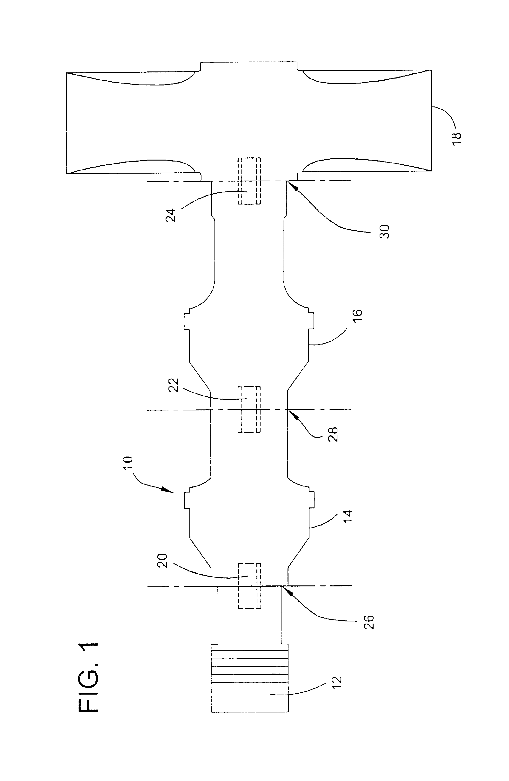
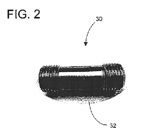
Ultrasonic horn assembly stack component connector
a technology of stack component and ultrasonic horn, which is applied in the direction of mechanical vibration separation, manufacturing tools, generators/motors, etc., can solve the problems of reducing the efficiency of energy transfer, affecting and forming high-pressure center contact areas, so as to reduce the maintenance requirements of stack component interfaces and efficient energy transfer
- Summary
- Abstract
- Description
- Claims
- Application Information
AI Technical Summary
Benefits of technology
Problems solved by technology
Method used
Image
Examples
example 1
Horn assembly components were assembled using connectors of this invention and, for comparison, analogous components were connected using a fully threaded stud according to the prior practice. In connecting the components, a torque of 30 ft-lbs was applied in each instance. An impression of each of the respective interfaces where the energy transfer faces were brought into engagement was taken by installing a pressure sensing film (Fuji brand prescale film) between interfaces between the respective components. The impression of an exemplary booster interface of the assembly of the invention is illustrated in FIG. 3, and shows a relatively uniform pressure pattern represented by the relatively uniform darkness of the impression. The comparative impression of a booster interface is illustrated in FIG. 4, and shows a non-uniform pressure pattern represented by non-uniform darkness, with a concentration of darkness and therefore pressure at a high-pressure contact center area surroundin...
example 2
Ultrasonic stack components were assembled and ultrasonically driven for 8 hours at a frequency of 20,000 Hz using the stud of the invention. For comparison purposes, stack components were connected using a fully threaded standard stud. Upon disassembly, the respective energy transfer faces were examined. FIG. 5 is a photograph of the energy transfer face of an exemplary stack component having been connected with the stud of the invention, then operated as described. It reveals a wear-free, oxidation-free interface. The comparative energy transfer face corresponding to connection using a standard, fully threaded stud is illustrated in FIG. 6, and reveals an uneven wear pattern, fretting, and oxidative burning.
example 3
The clamping forces generated by the connector of the invention and fully threaded comparative connector discussed in Examples 1 and 2 were computer modeled using finite element analysis, and illustrations prepared therefrom are presented in FIGS. 7 and 8. FIG. 7 shows that with the invention the clamping forces are distributed relatively uniformly across the interface. FIG. 8 shows that with a conventional, fully threaded stud, a signficant portion of the clamping forces concentrates around the stud at the interface, and a significant portion radiates away from the interface.
PUM
| Property | Measurement | Unit |
|---|---|---|
| width | aaaaa | aaaaa |
| diameter | aaaaa | aaaaa |
| frequency | aaaaa | aaaaa |
Abstract
Description
Claims
Application Information
 - R&D
- Intellectual Property
- Life Sciences
- Materials
- Tech Scout
- Unparalleled Data Quality
- Higher Quality Content
- 60% Fewer Hallucinations
Browse by: Latest US Patents, China's latest patents, Technical Efficacy Thesaurus, Application Domain, Technology Topic, Popular Technical Reports.
© 2025 PatSnap. All rights reserved.Legal|Privacy policy|Modern Slavery Act Transparency Statement|Sitemap|About US| Contact US: help@patsnap.com


