Apparatus and method used in disk drive for driving spindle motor

a technology of disk drive and spindle motor, which is applied in the direction of motor/generator/converter stopper, dynamo-electric converter control, instruments, etc., can solve the problems of increasing power consumption and difficulty in, for example, starting up the motor, and achieve the effect of boosting the power supply voltag

Inactive Publication Date: 2005-01-11
KK TOSHIBA
View PDF17 Cites 19 Cited by
  • Summary
  • Abstract
  • Description
  • Claims
  • Application Information

AI Technical Summary

Benefits of technology

According to an embodiment of the invention, there is provided a disk drive using a disk as a recording medium. The disk drive comprises a spindle motor, driver circuit, first control circuit, second control circuit, voltage booster, voltage selector and controller. The spindle motor rotates the disk. The driver circuit drives the spindle motor by supplying a current to the spindle motor. The first control circuit controls the spindle motor via the driver circuit to start up the spindle motor in a first mode. The second control circuit controls the spindle motor via the driver circuit to rotate the spindle motor at a rated speed in a second mode. The voltage booster boosts a power supply voltage from a disk drive power supply. The voltage selector selects, in the first mode as a voltage applied to the driver circuit, the power supply voltage boosted by the booster, and selects, in the second mode as the voltage applied to the driver circuit, the power supply voltage from the disk drive power supply. The controller sets the first mode to start up the spindle motor, and sets the second mode when the spindle motor has been started up.

Problems solved by technology

However, if the spindle motor is powered by a high voltage for a long period of time, the power consumption increases.
However, if the voltage of the power supply for the disk drive is reduced, it is difficult to, for example, start up the motor when the disk drive is turned on.

Method used


Image

  • Apparatus and method used in disk drive for driving spindle motor
  • Apparatus and method used in disk drive for driving spindle motor
  • Apparatus and method used in disk drive for driving spindle motor

Examples


Embodiment Construction

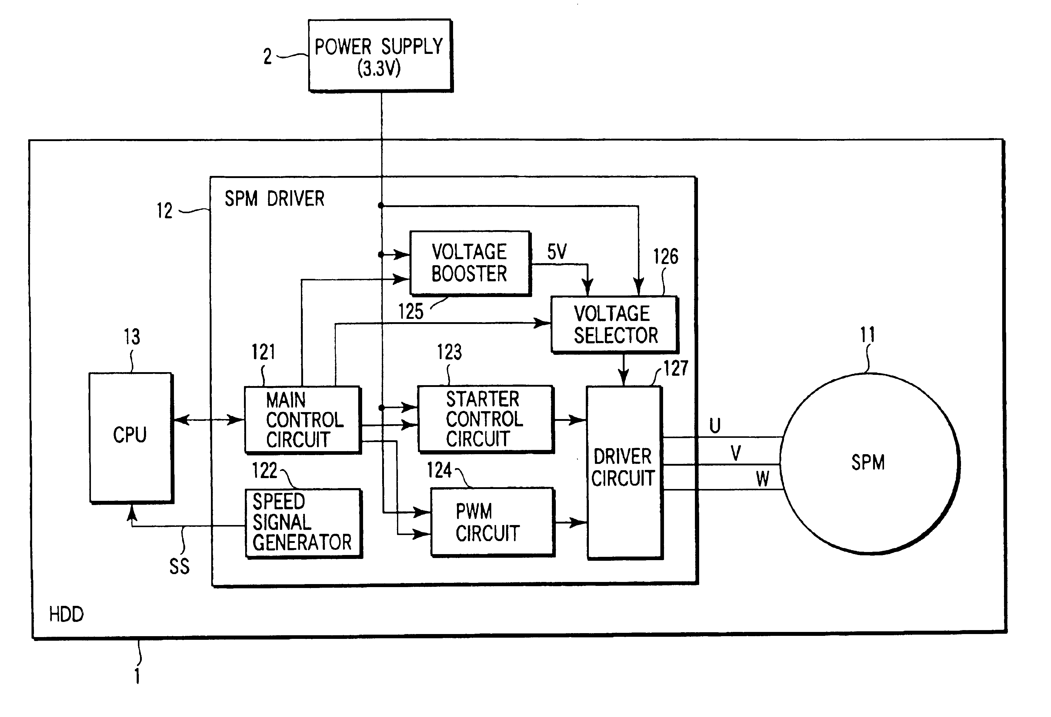
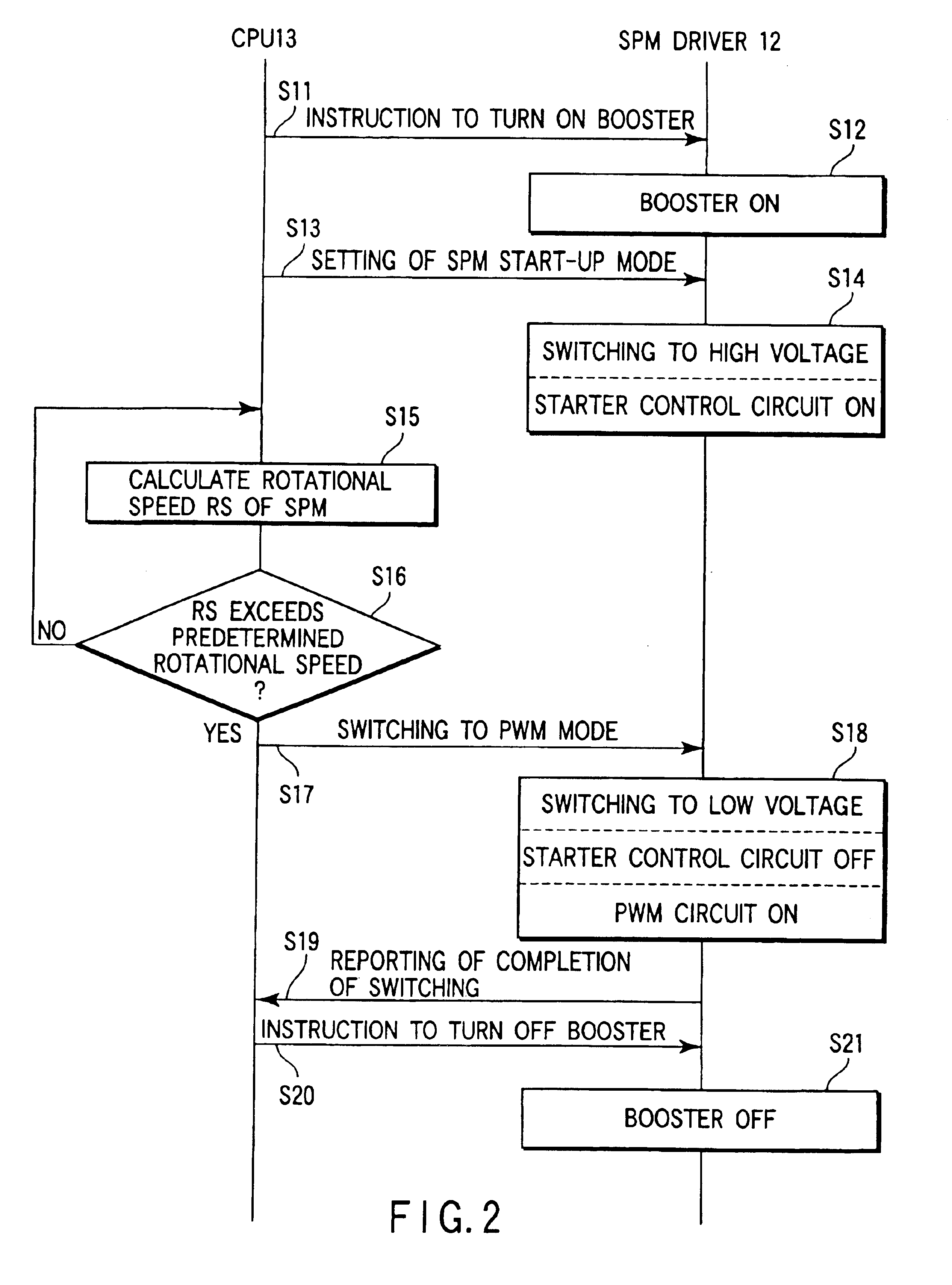
Referring to the accompanying drawings, a description will be given of an embodiment in which the invention is applied to a hard disk drive.

FIG. 1 is a block diagram illustrating the configuration of a hard disk drive (hereinafter referred to as an “HDD”) 1 according to the embodiment of the invention. The HDD 1 of FIG. 1 is connected to a power supply (low voltage power supply) 2 represented by a battery. The voltage of the power supply 2 is, for example, 3.3V, which is lower than a conventional power supply voltage of 5V.

The HDD 1 comprises a spindle motor (hereinafter referred to as a “SPM”) 11, SPM driver 12 and CPU 13. The SPM 11 rotates magnetic disks (not shown) used as a recording medium for the HDD 1. The SPM 11 has a three-phase, twelve-pole motor coil expressed by, for example, U, V and W. The SPM driver 12 supplies current to the SPM 11 to drive it. The CPU 13 is a controller for controlling each component of the HDD 1 in accordance with a control program stored in a non...


PUM

PropertyMeasurementUnit
voltageaaaaaaaaaa
voltageaaaaaaaaaa
voltageaaaaaaaaaa

Abstract

A CPU sets an SPM driver in SPM start-up mode when a SPM is started up. At this time, a voltage selector applies, to a driver circuit, a voltage (high voltage) boosted by a voltage booster. A starter control circuit controls, during the period of an SPM start-up mode, the driver circuit with the high voltage applied thereto, thereby starting up the SPM. After the SPM has been started up, the CPU sets the SPM driver in PWM mode. At this time, the voltage selector switches the voltage applied to the driver circuit, from the boosted voltage to the voltage (low voltage) of a power supply. During the period of the PWM mode, a PWM circuit controls the driver circuit with the low voltage applied thereto, so as to rotate the SPM at a rated speed.

Description

CROSS-REFERENCE TO RELATED APPLICATIONSThis application is based upon and claims the benefit of priority from the prior Japanese Patent Application No. 2002-223522, filed Jul. 31, 2002, the entire contents of which are incorporated herein by reference.BACKGROUND OF THE INVENTION1. Field of the InventionThe present invention relates to a disk drive using a disk as a recording medium, and more particularly to an apparatus and method for driving a spindle motor to rotate the disk, having a low power consumption.2. Description of the Related ArtIn general, disk drives using disks as a recording medium utilize a motor, called a spindle motor, to rotate the disks at high speed. Spindle motors are brushless DC motors. The power supply voltage for disk drives is directly used as that for the spindle motor. The power supply voltage for disk drives is generally a high voltage sufficient to reliably drive the spindle motor. However, if the spindle motor is powered by a high voltage for a long ...

Claims


Application Information

Patent Timeline
Patent Type & Authority Patents(United States)
IPC IPC(8): G11B19/28G11B19/20H02P6/06H02P6/08H02P6/17H02P6/20
CPCG11B19/28G11B19/2054
Inventor NAKABAYASHI, YOICHI
Owner KK TOSHIBA
Why Eureka
Try Eureka