Motor drive device and drive method

a technology of motor drive and drive device, which is applied in the direction of motor/generator/converter stopper, electronic commutator, dynamo-electric converter control, etc., can solve the problems of device damage, power supply voltage rise, and difficulty in reducing device size and cost, so as to prevent power supply voltage rise

Inactive Publication Date: 2007-06-07
COLLABO INNOVATIONS INC
View PDF6 Cites 18 Cited by
  • Summary
  • Abstract
  • Description
  • Claims
  • Application Information

AI Technical Summary

Benefits of technology

[0016] The present invention is directed to solving this problem by preventing a power supply voltage rise caused by motor current flowing back to the power supply.

Problems solved by technology

A problem with the regeneration phase of the related art is that because motor current flows back to the power source after the next urging period starts, the power supply voltage rises and can lead to device damage.
Reducing device size and cost is also difficult with the related art because a capacitance to improve the current sink capacity of the power supply, a zener diode for voltage clamping, or some other external protection device is required to prevent a rise in the power supply voltage.

Method used


Image

  • Motor drive device and drive method
  • Motor drive device and drive method
  • Motor drive device and drive method

Examples


first embodiment

[0037] A motor drive device according to this first embodiment of the invention drives a three-phase motor by supplying drive power for driving the motor based on PWM (pulse width modulation) control of each phase coil of the motor.

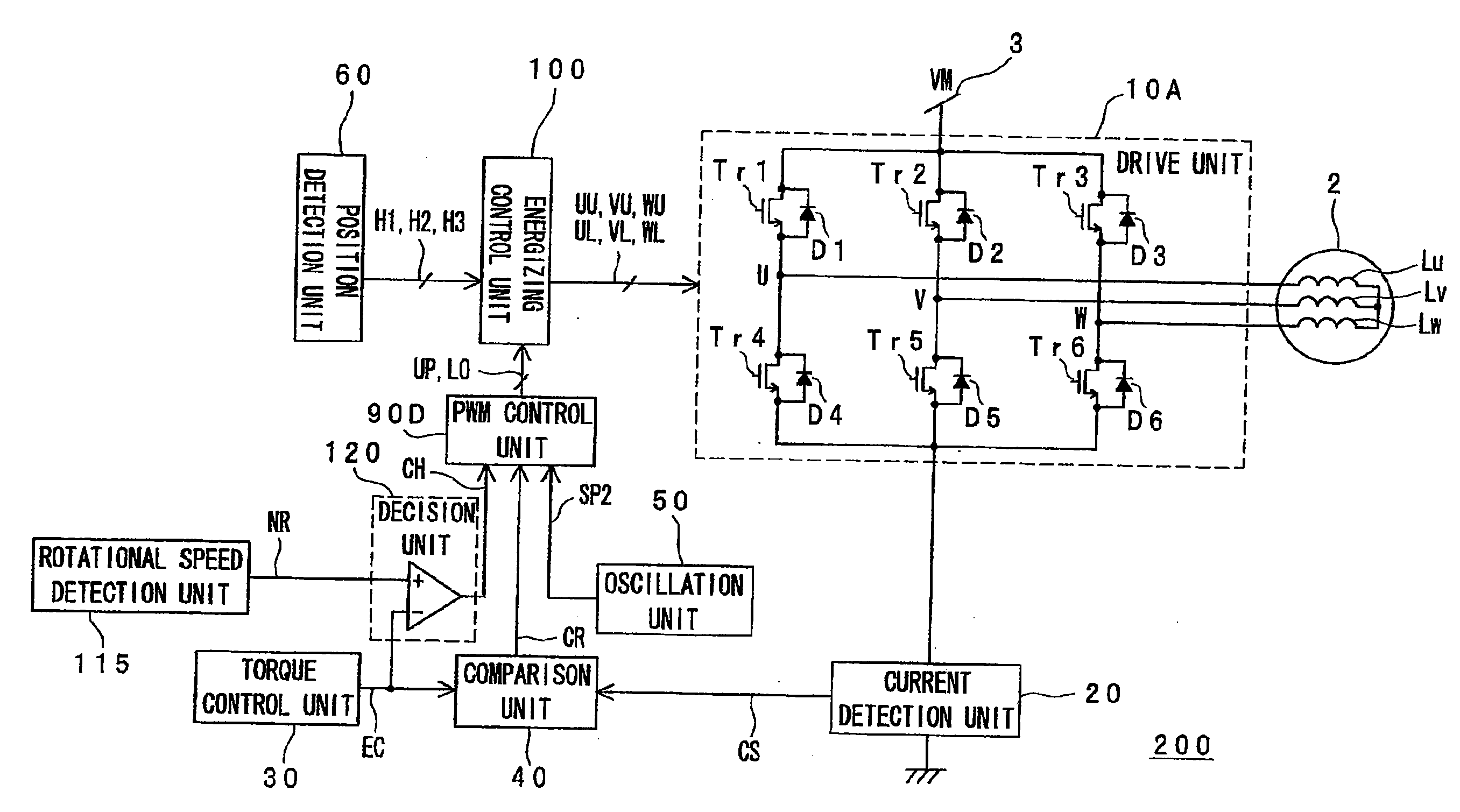
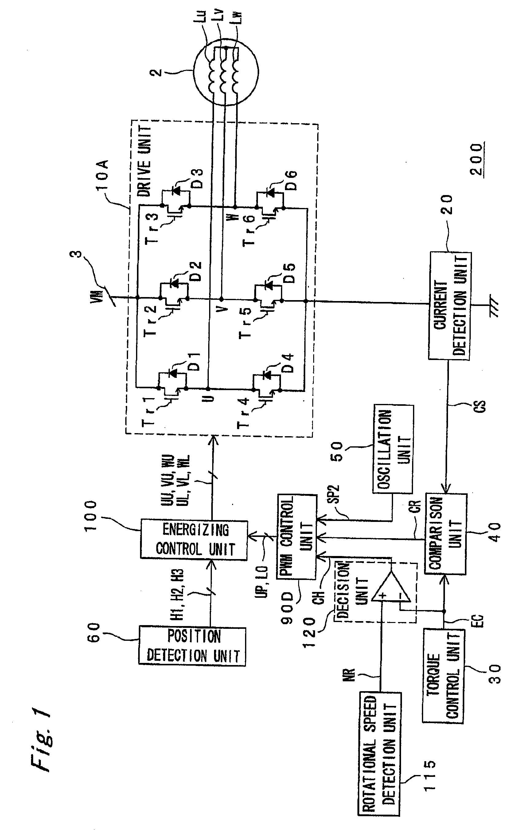
[0038] In the first embodiment of the invention motor control content changes when the level of the torque control signal that sets the torque level of the motor goes below the level of the rotational speed signal that denotes the speed of the motor. This prevents the backflow of the motor current flowing through the motor coil, and prevents a rise in the power supply voltage that could result in damage to other components. The first embodiment of the invention is described with reference to FIG. 1 to FIG. 4. FIG. 1 is a block diagram of the motor drive device 200 in this first embodiment of the invention. The motor drive device 200 according to this first embodiment of the invention includes a power supply 3, a drive unit 10A, a current detection unit 2...

second embodiment

[0095] A motor drive device that uses a current controlled PWM drive arrangement is described in the first embodiment above, but the invention can also be applied to voltage controlled PWM drive arrangements. A first aspect of a voltage controlled PWM drive arrangement according to the present invention is described in this second embodiment of the invention below with reference to FIG. 5 to FIG. 7. Primarily the differences between this embodiment and the first embodiment are described below wherein like parts are identified by like reference numerals and further description thereof is omitted.

[0096] The motor drive device 450 shown in FIG. 5 drives a motor 2 by a drive unit 10A having a three-phase bridge configuration. The voltage detected from detection resistance 409 is input through low-pass filter 408 to amplifier 407.

[0097] The amplifier 407 amplifies the difference between the torque control signal EC set by the torque control unit 30 and the output voltage of the low-pas...

third embodiment

[0119] A third embodiment of the invention is described below with reference to FIG. 8 to FIG. 10. This embodiment of the invention differs from the first embodiment in the arrangement of the energizing control unit 100 and the arrangement for generating the drive signals UU-WL.

[0120] The motor drive device 250 according to this embodiment of the invention includes a PWM control unit 90E that differs internally from the arrangement of the PWM control unit 90D and an energizing control unit 100B that differs internally from the arrangement of the energizing control unit 100 in the motor drive device 200 of the first embodiment. Other aspects of the arrangement and operation of this embodiment are the same as described in the first embodiment. Like parts and signals in this third embodiment of the invention are also identified by the same reference numerals shown in FIG. 1.

[0121]FIG. 8 is a block diagram showing the arrangement of the motor drive device 250 in this third embodiment ...


PUM


Abstract

A rise in the power supply voltage as a result of a sudden speed reducing command causing the motor current to flow to the power supply is prevented. The motor drive device has a drive signal generating unit for generating a drive signal by an energizing control unit, PWM control unit, and oscillation unit; a drive unit for producing drive power to drive the motor based on the drive signal; a torque control signal generating unit for generating a torque control signal specifying the motor torque; a speed detection unit for detecting the rotational speed of the motor and generating a rotational speed signal denoting motor speed information; and a decision unit for generating a speed difference detection signal denoting the difference between the torque control signal and the rotational speed signal. The drive signal generating unit is controlled based on the speed difference detection signal.

Description

BACKGROUND OF THE INVENTION [0001] 1. Field of Invention [0002] The present invention relates to technology for preventing a rise in the power supply voltage in a drive circuit for driving a motor. [0003] 2. Description of Related Art [0004] Pulse width modulation (PWM) drive methods that control energizing the motor coil by controlling the on / off state of specific switching devices in the motor drive circuit are commonly used to drive brushless motors in AV equipment. U.S. Pat. No. 5,309,078 (corresponding to Japanese Unexamined Patent Appl. Pub. H5-211780, and E.P. Publication No. 525,999), for example, teaches a widely used synchronous rectifier PWM drive technology for achieving low loss and high efficiency PWM drive. [0005] The PWM drive technology taught in U.S. Pat. No. 5,309,078 is described more fully below with reference to FIG. 12. FIG. 12 shows part of a three-phase motor system that is driven by a drive unit 305 composed of a three-phase bridge. [0006] The voltage detec...

Claims


Application Information

Patent Timeline
Patent Type & Authority Applications(United States)
IPC IPC(8): H02P7/00H02P6/06H02P6/08H02P6/12H02P6/17
CPCH02P27/08
Inventor TAKATA, GOMORI, HIDEAKIYAMAMOTO, YASUNORI
Owner COLLABO INNOVATIONS INC
Why Eureka
Try Eureka