Charging Control Apparatus and Charging Apparatus

a charging control and charging technology, applied in the integration of power network operation systems, emergency power supply arrangements, relays, etc., can solve the problems of power consumption and achieve the effect of increasing the power supply voltag

Active Publication Date: 2010-01-07
SEMICON COMPONENTS IND LLC
View PDF5 Cites 19 Cited by
  • Summary
  • Abstract
  • Description
  • Claims
  • Application Information

AI Technical Summary

Benefits of technology

[0007]A charging control apparatus according to an aspect of the present invention, comprises: a voltage control unit in a charging apparatus configured to control generation of an output voltage and a power supply voltage, the charging apparatus being an apparatus configured to generate, from a voltage of an input power supply applied through a relay, the output voltage for charging a battery and the power supply voltage for control; and a relay control unit operated by the power supply voltage, the relay control unit configured to drive the relay so as to stop applying the voltage of the input power supply to the charging apparatus, when detecting a standby state in which the battery is not being charged, and drive the relay so as to increase the power supply voltage by applying the voltage of the input power supply to the charging apparatus, when the power supply voltage decreases below a predetermined level.

Problems solved by technology

However, even when the charging apparatus is in the standby state where the production of the output voltage is stopped, the voltage of the AC power supply is applied to the primary side of the circuit, and power continues to be consumed in a rectification circuit and the like.

Method used


Image

  • Charging Control Apparatus and Charging Apparatus
  • Charging Control Apparatus and Charging Apparatus
  • Charging Control Apparatus and Charging Apparatus

Examples


Embodiment Construction

[0012]At least the following details will become apparent from descriptions of this specification and of the accompanying drawings.

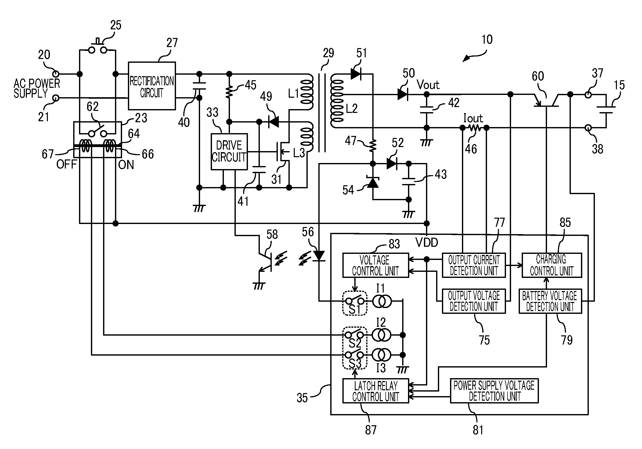
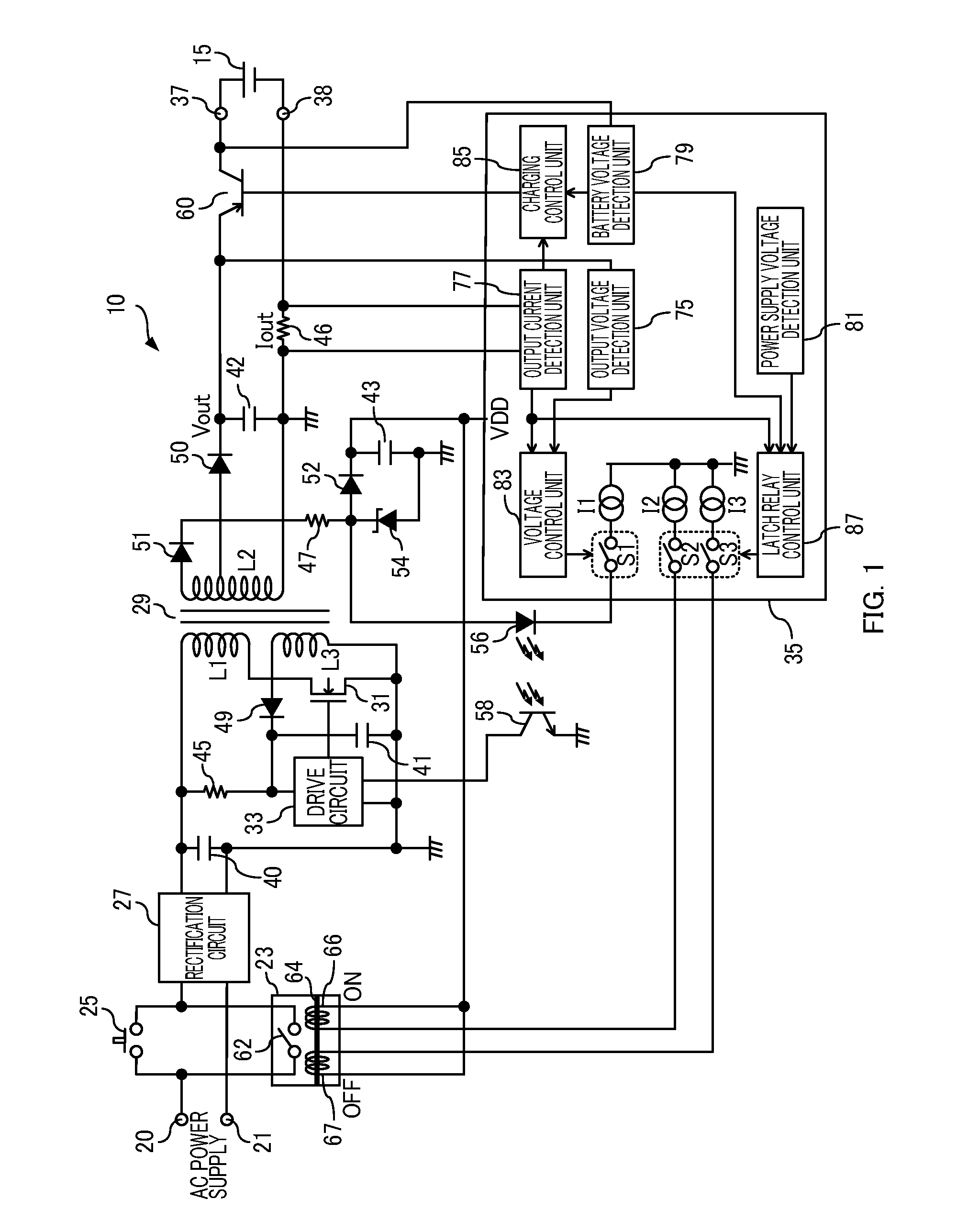
[0013]FIG. 1 is a diagram showing a configuration of a charging apparatus according to an embodiment of the present invention. The charging apparatus 10 is an apparatus to be used for charging a battery 15 in an electronic apparatus such as a cellular telephone. The charging apparatus 10 includes input terminals 20 and 21, a latch relay 23 of a latch type, for example, a push switch 25, a rectification circuit 27, a transformer 29, an N-channel MOSFET 31, a drive circuit 33, a control IC (integrated circuit) 35, output terminals 37 and 38, capacitors 40 to 43, resistors 45 to 47, diodes 49 to 52, a Zener diode 54, a light-emitting diode 56, a phototransistor 58 and a PNP transistor 60.

[0014]The latch relay 23 is a relay circuit that can maintain an ON / OFF state without current consumption. The latch relay 23 includes an iron piece 62, an iron core 64, an...


PUM


Abstract

A charging control apparatus comprising: a voltage control unit in a charging apparatus configured to control generation of an output voltage and a power supply voltage, the charging apparatus being an apparatus configured to generate, from a voltage of an input power supply applied through a relay, the output voltage for charging a battery and the power supply voltage for control; and a relay control unit operated by the power supply voltage, the relay control unit configured to drive the relay so as to stop applying the voltage of the input power supply to the charging apparatus, when detecting a standby state in which the battery is not being charged, and drive the relay so as to increase the power supply voltage by applying the voltage of the input power supply to the charging apparatus, when the power supply voltage decreases below a predetermined level.

Description

CROSS-REFERENCE TO RELATED APPLICATION[0001]This application claims the benefit of priority to Japanese Patent Application No. 2008-174694, filed Jul. 3, 2008, of which full contents are incorporated herein by reference.BACKGROUND OF THE INVENTION[0002]1. Field of the Invention[0003]The present invention relates to a charging control apparatus and a charging apparatus.[0004]2. Description of the Related Art[0005]In a charging apparatus for charging a battery in an electronic apparatus such as a cellular telephone, a voltage of an AC power supply to be applied to the primary side is rectified to produce a direct-current voltage, and a transformer is driven by this direct-current voltage, so that an output voltage for charging the battery is generated on the secondary side (see Japanese Patent Laid-Open Publication 2007-166825, for example).[0006]In order to reduce power consumption, such a charging apparatus may stop producing the output voltage when the completion of charging is det...

Claims


Application Information

Patent Timeline
Patent Type & Authority Applications(United States)
IPC IPC(8): H02J7/04
CPCH02J9/005H02J7/0065H02J2207/20Y02B70/30Y04S20/20
Inventor ARAI, NOBUHIROKURIHARA, KOUITI
Owner SEMICON COMPONENTS IND LLC
Why Eureka
Try Eureka