Vehicular mirror angle controller

a controller and mirror technology, applied in the direction of motor/generator/converter stopper, dynamo-electric converter control, instruments, etc., can solve the problems of affecting reducing the detection efficiency of the controller, so as to improve the detection performance and simplify the circuit arrangement

Inactive Publication Date: 2005-01-11
MURAKAMI CORP
View PDF13 Cites 9 Cited by
  • Summary
  • Abstract
  • Description
  • Claims
  • Application Information

AI Technical Summary

Benefits of technology

It is an exemplified general object of the present invention to provide a vehicular mirror angle controller in which performance in detection can be improved, and an arrangement of circuitry can be simplified.

Problems solved by technology

Consequently, the driver would disadvantageously be deprived of comfort and convenience each time.
However, in this arrangement, repeated operations of tilting the mirror in synchronization with the reverse gear shift would disadvantageously cause the mirror to be gradually shifted out of a proper position.
Since the angular displacement which takes place when the mirror coasts in the normal direction is in many instances different from that which takes place when the mirror coasts in the reverse direction, a plurality of tilting motions of the mirror alternately repeated in the normal and reverse directions would result in accumulation of residuals derived from the difference in the angular displacements of the coasting mirror, whereby the tilt angle of the mirror would disadvantageously shift by degrees.
However, changing a viewable range of the mirror through operation of the above-mentioned angle-adjusting actuator is not an easy task especially upon getting into an expressway.
In Prior Art 2, however, like the above Prior Art 1, the same problem would be encountered; i.e., a plurality of rotary motions of the tilt motor alternately repeated in the normal and reverse directions would disadvantageously cause the tilt angle of the mirror to be gradually shifted out of a proper position.
Such conventional mirror angle controllers however involve the drawback of allowing the mirror angle to be gradually shifted through repeated operations of tilting the mirror angle in synchronism with the reverse gear or the blinker.
With the arrangement as disclosed in Prior Art 3 as indicated by the circuit diagram in FIG. 2, since the two pickup coils L1, L2 provided in the feed lines to the vertical motion motor M2 could be subject to interaction with each other, the detected high-frequency signals would disadvantageously be reduced by half in magnitude, and resulting desensitization of the detector 7 would lead to errors in mirror angle control, and accumulation of such errors.
In addition, the both of the pickup coils and waveform-shaping parts need be separately equipped for detection upon normal rotation and for detection upon reverse rotation respectively, and thus the arrangement of the circuit need be more complicated, which would inevitably increase cost.

Method used


Image

  • Vehicular mirror angle controller
  • Vehicular mirror angle controller
  • Vehicular mirror angle controller

Examples


Embodiment Construction

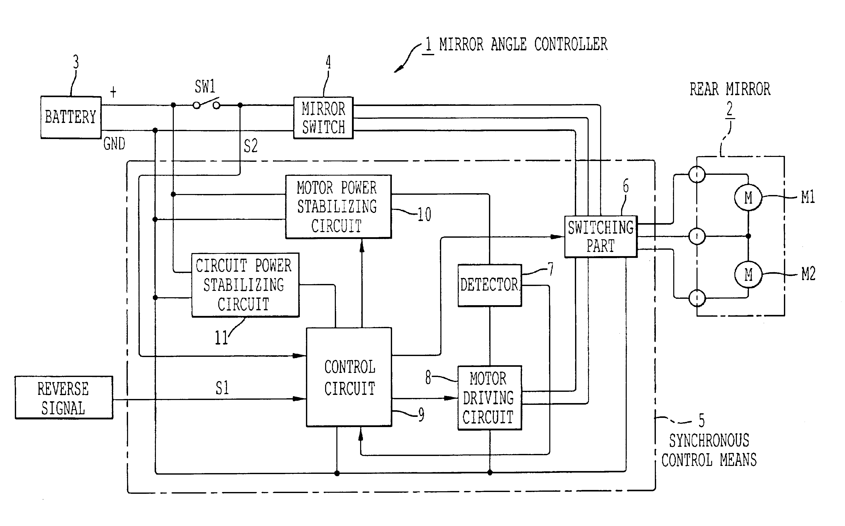
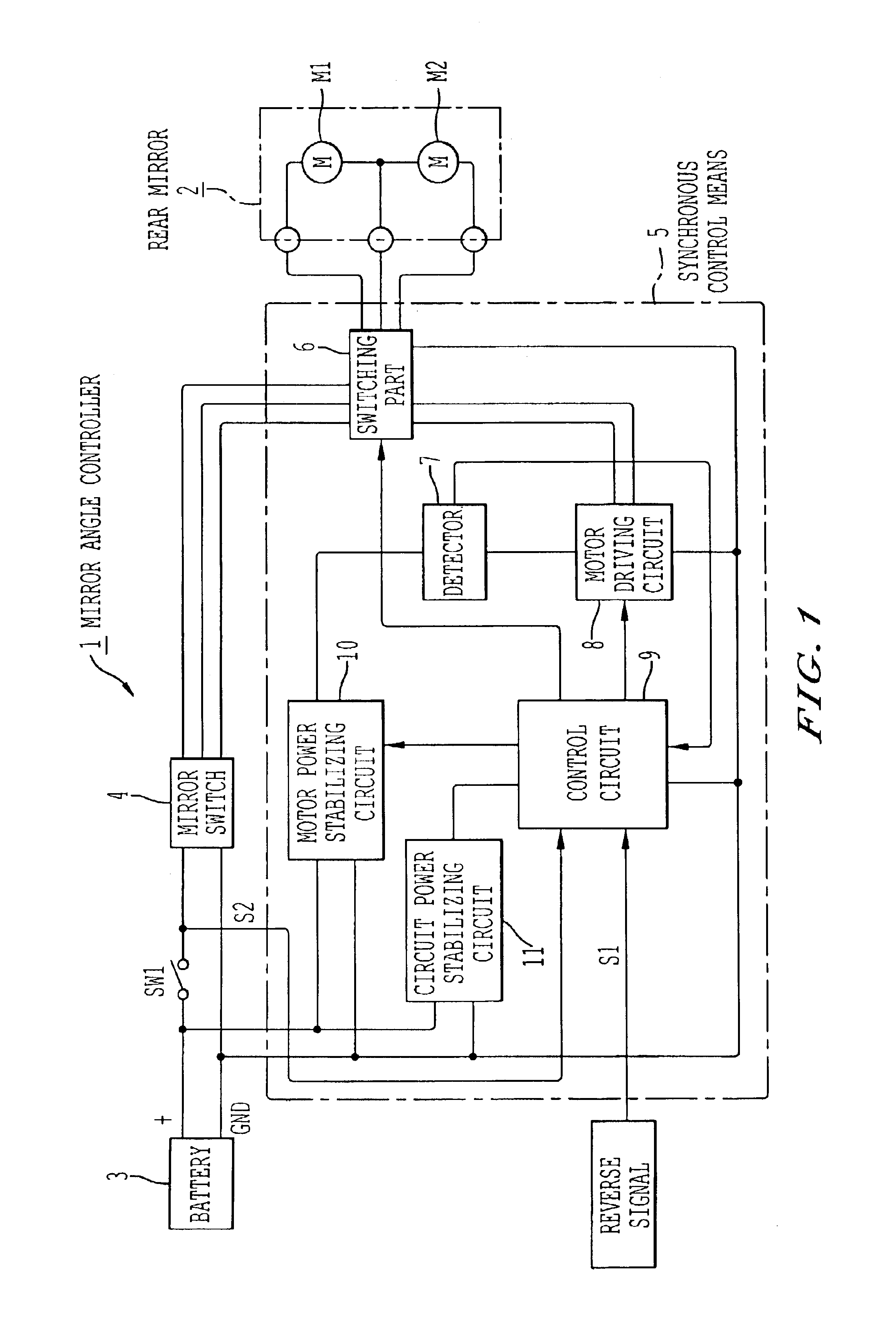
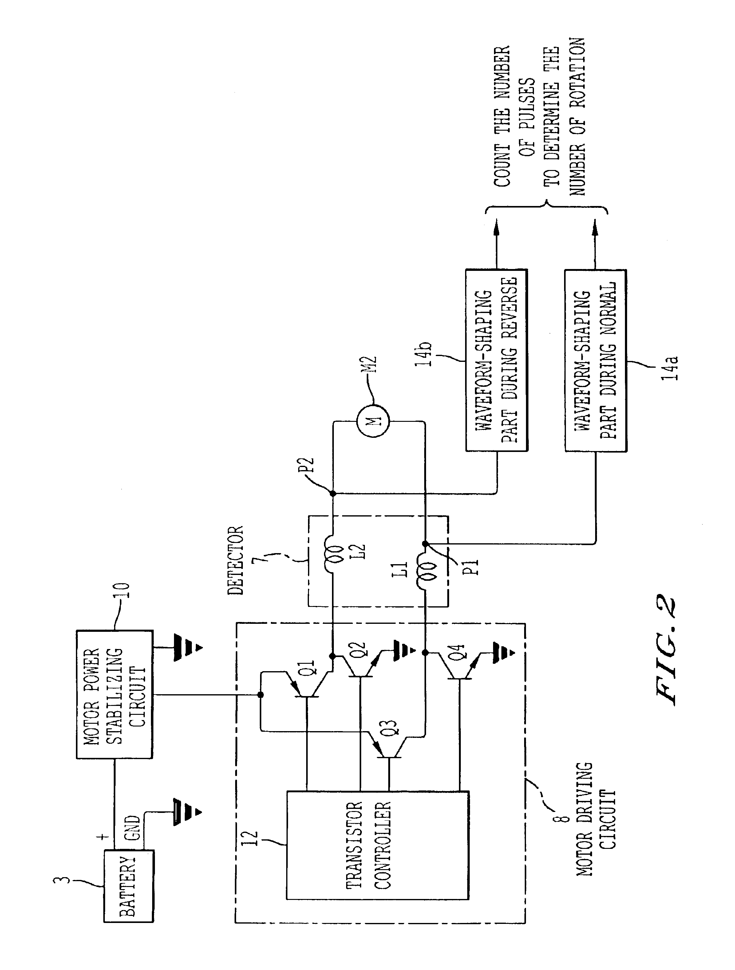
A preferred embodiment of the present invention will now be described with reference to the drawings. FIG. 1 is a block diagram showing an arrangement of a mirror angle controller 1 according to one exemplified embodiment of the present invention, and a rearview mirror 2, and FIG. 4 is a circuit diagram showing the arrangement more specifically. As shown in FIGS. 2 and 4, the mirror angle controller 1 reversibly controls rotation of a lateral motion motor M1 and a vertical motion motor M2 mounted in the rearview mirror 2 through manual operation, and adjusts a tilt angle of the rearview mirror 2 to a desired angle.

Further, the mirror angle controller 1 normally rotates the vertical motion motor M2 to allow the mirror to automatically tilt to a desired set position when a reverse signal (external signal) outputted upon operation of the shift lever of the vehicle to slip the gear into reverse (Reverse gear) is given, so that the driver can be provided with a view of the area near a re...


PUM


Abstract

In response to an operation of reversing a vehicle, a tilt motor is rotated by a specific amount in a normal direction to tilt a mirror angle to a position that permits a mirror to provide the driver with a view of the area near a rear wheel of the vehicle, while in response to an operation of releasing the reverse gear, the tilt motor is rotated by a specific amount in a reverse direction to restore the tilt angle to a normal position thereof. During the operations, a high-frequency signal generated upon switching a brush of the motor is detected using a pickup coil to determine an amount of rotation of the motor. One and the same pickup coil may be used for detection during both of normal and reverse rotations. A voltage of a battery 3 is stabilized in a motor power stabilizing circuit 10, and supplied via a motor driving circuit 8 to a tilt motor M2. Polarity of the voltage outputted from the motor power stabilizing circuit 10 is fixed. Polarity of the voltage outputted from the motor driving circuit 8 is switchable according to a switching operation of the motor driving circuit 8 based upon a driving direction instruction. The pickup coil L10 is provided between the motor power stabilizing circuit 10 and the motor driving circuit 8.

Description

FIELD OF THE INVENTIONThis invention relates to a vehicular mirror angle controller that controls a tilt angle of a mirror for a vehicle, such as a door mirror and a sideview mirror.DESCRIPTION OF RELATED ARTSIn general, passenger automobiles, station wagons, trucks and other vehicles are equipped with door mirrors, sideview mirrors or other types of rearview mirrors to provide the driver with a view of the area behind the vehicle for safety reasons. Such rearview mirrors typically include an angle-adjusting actuator with a remote control for setting a mirror angle at a position suitable for the driver, so that the driver may adjust the mirror angle to his / her preferred position or orientation by operating the remote control in the driver's seat.When the driver is backing a vehicle for example into a garage, the driver is preferably provided with a view of the area near a rear wheel of the vehicle. With the aforementioned angle-adjusting actuator, however, in order to tilt the mirro...

Claims


Application Information

Patent Timeline
Patent Type & Authority Patents(United States)
IPC IPC(8): B60R1/062B60R1/07B60R1/072
CPCB60R1/07
Inventor YAMADA, AYAKONAGAO, MITUYOSHISATO, HIDENORI
Owner MURAKAMI CORP
Why Eureka
Try Eureka