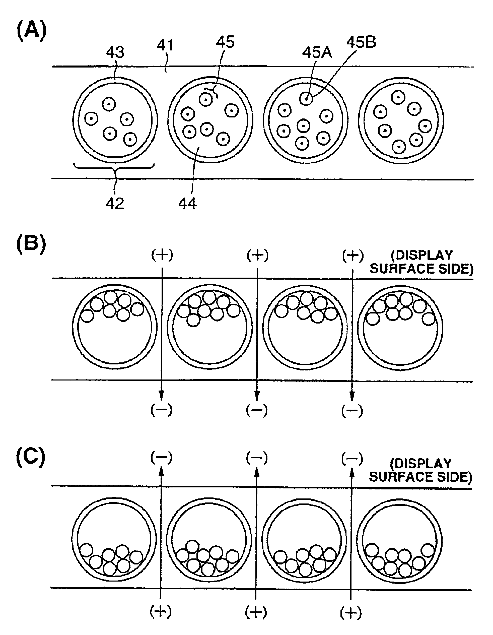
In the present invention, the maintenance of the distribution state will suffice so as long as it is within the permissible deflection for obtaining a desired display precision; in other words, the distribution position of charged particles does not have to be completely secured so as long as the distribution state of particles can be substantially maintained. For instance, the charged particles are contained in a microcapsule together with liquid for dispersing such charged particles. The charged particles may be of a
single type, or a mixture of a plurality of types, and may also be of a
composite structure to be contained in a microcapsule.
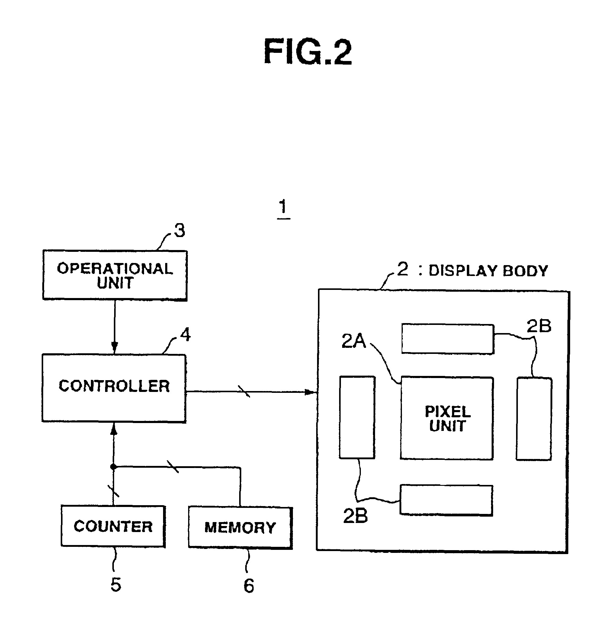
Here, the driver for controlling the switching element shall mean a data driver to be connected to the data line and a scan driver to be connected to the
scan line of the pixel unit in many cases. The writing of data will realize low
energy consumption by selecting and rewriting only the pixels for rewriting data.
In the present invention, the refresh circuit does not necessarily once clear (delete) the data of images and characters generating the distribution of the charged particles. In other words, with the display device of the present invention,
voltage is applied upon initially displaying the image, and, thereafter, the
relative density of the particles and liquid is approximately the same, and the distribution state of charged particles can be maintained even when the application of
voltage is released. In this type of display device, with the purpose of stabilizing or maintaining the
initial distribution state of charged particles upon having applied voltage to charged particles, voltage merely needs to be applied periodically or occasionally based on the image data. That is, different from the “refresh” implying the deletion and writing of data conducted conventionally with
liquid crystal displays, it is not necessarily imperative to delete the data in the present invention. As the display device of the present invention also functions as
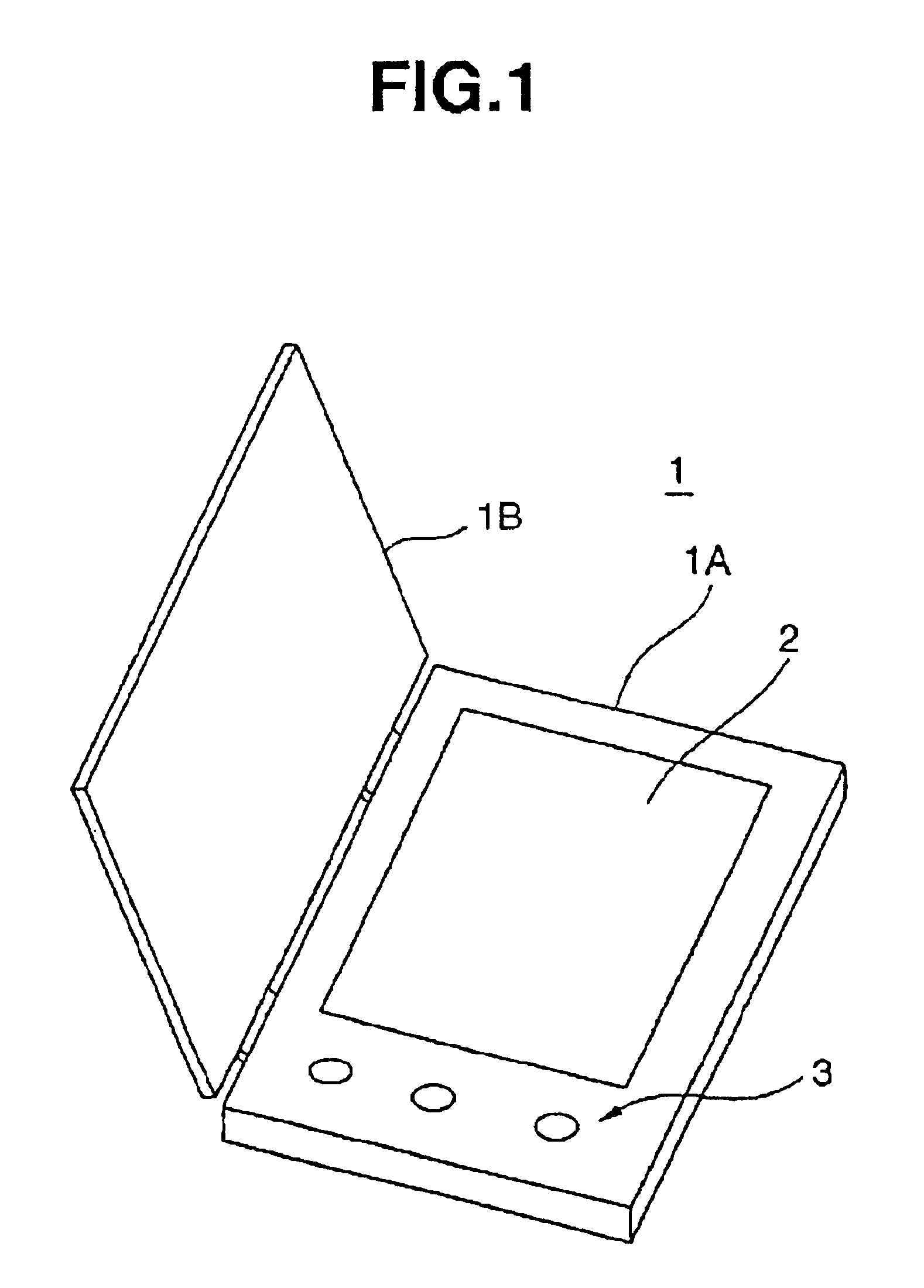
electronic paper; in other words, since it comprises a function of displaying image and character information as is in correspondence to the distribution of charged particles for a prescribed period of time after applying voltage to the charged particles in accordance with image data, the present invention also corresponds to a recording medium. With the display device structured of at least a display unit, which is the recording medium, and
peripheral circuits containing the voltage application circuit, for example, even upon removing the display unit from the
peripheral circuits, it would still be possible for users to confirm the information displayed on this
electronic paper at home, in the office, and so on. Further, for instance, upon employing the present invention in a car
navigation system, it would be possible for a user to remove the portion (electronic paper) displaying the map upon having arrived at a
parking space nearby one's destination from the
peripheral circuit, and bring it along while he / she walks to the destination.

