Flexible circuit adhered to metal frame of device

Inactive Publication Date: 2005-01-11
SCHNEIDER ELECTRIC JAPAN
View PDF25 Cites 15 Cited by
  • Summary
  • Abstract
  • Description
  • Claims
  • Application Information

AI Technical Summary

Benefits of technology

A principal object of the present invention to allow the placement of electronic components that are used to control a particular electrical device in an electrical circuit breaker, such as an actuator or a solenoid, directly onto the housing of that device without requiring a significant amount of additional space.
Another object of the invention is to provide a more efficient heat dissipation environment for dissipating heat generated by the control circuitry, without having to add extra components such as, for example, a cooling fan. A related object is to reduce the dielectric separation between the electronic components and a heat sink.

Problems solved by technology

This arrangement can create problems when space becomes critical because space must be provided not only for the mounting of the circuit board but also to allow for the installation of the board and the wires that connect it to the device it is controlling.

Method used


Image

  • Flexible circuit adhered to metal frame of device
  • Flexible circuit adhered to metal frame of device
  • Flexible circuit adhered to metal frame of device

Examples


Embodiment Construction

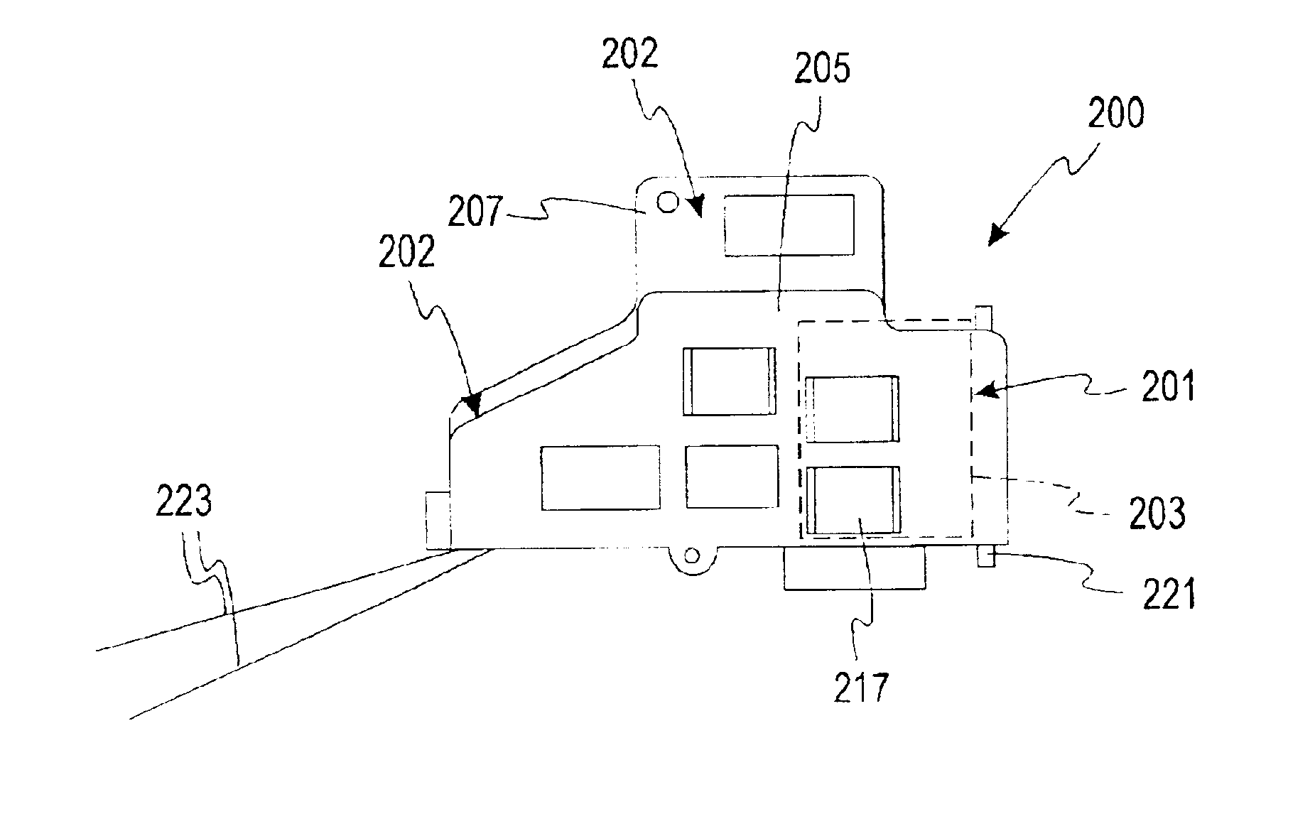
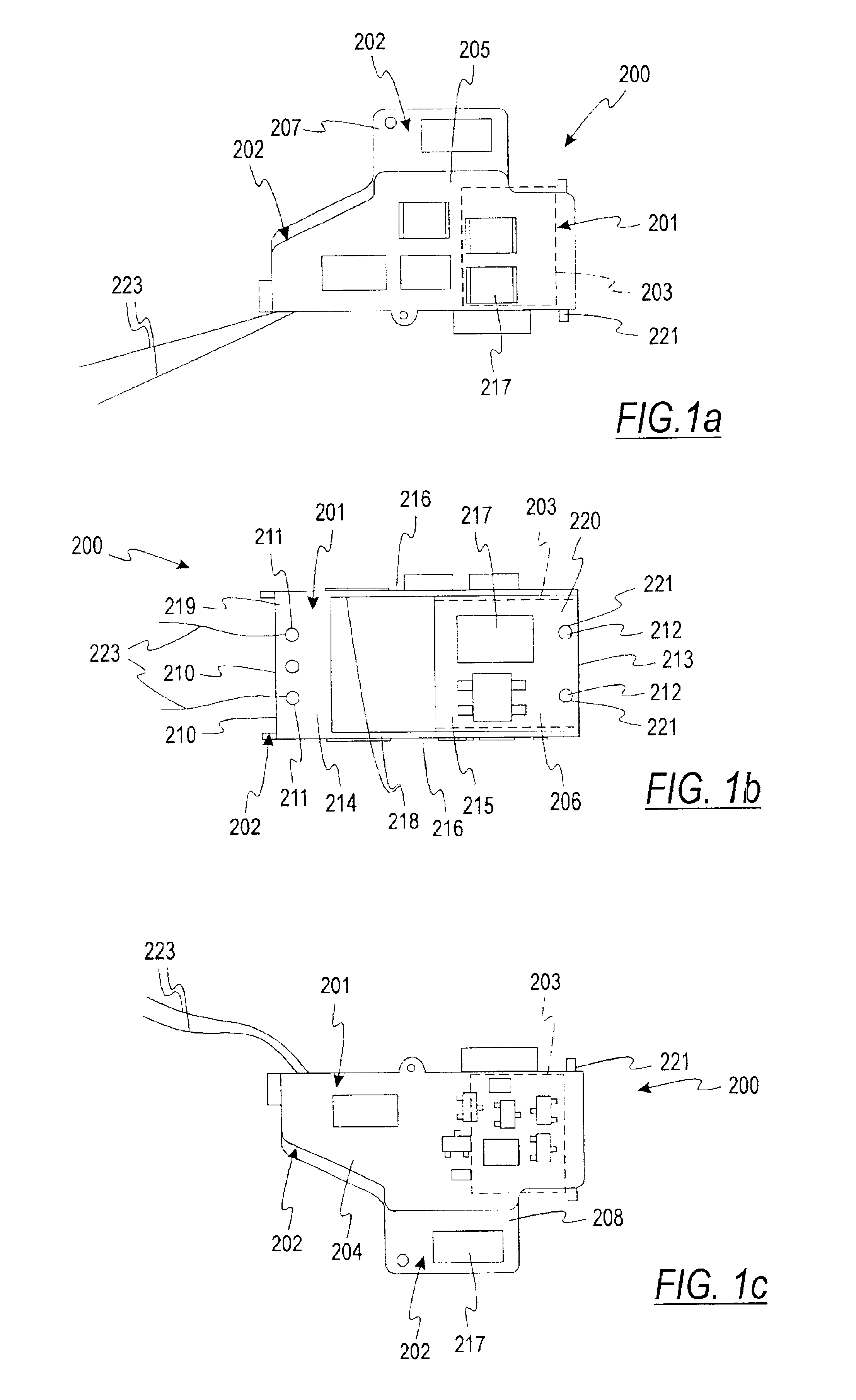
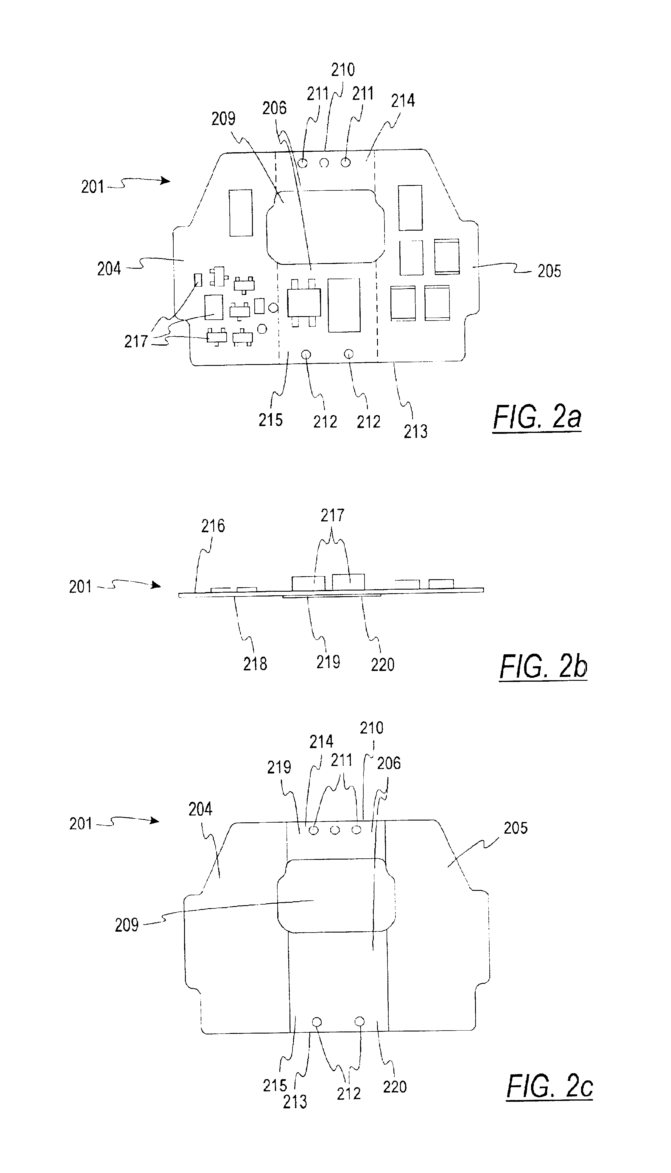
Referring now to the drawings, an under voltage release 200 comprises a flexible circuit board 201, a metal C-frame 202, and a solenoid 203. The flexible circuit board 201 has a first end section 204 and a second end section 205 that are mirror images of each other, being connected to each other by a joining section 206 (see FIG. 2c). The first end section 204 has a generally rectangular shape that approximately resembles the shape of a first frame surface 207 (see FIG. 3a). Similarly, the second end section 205 has a generally rectangular shape that approximately resembles the shape of a second frame surface 208 (see FIG. 3c).

The joining section 206 is rectangularly shaped, having a rectangular aperture 209 positioned near a lead wire end 210, two lead wire holes 211 positioned near the lead wire end 210, and two solenoid holes 212 positioned near a solenoid end 213. A small bridge part 214 forms the part of the joining surface 206 that is towards the lead wire end 210 and a big br...


PUM


Abstract

An electrical device having a heat conductive housing has a flexible circuit board attached to the surface of the housing to control or take readings from the electrical. The flexible circuit board preferably has an adhesive coating on at least a portion of one side for adhering the flexible circuit board to the surface of the metal housing. At least one component mounted on the flexible circuit breaker generates heat, which is dissipated via the conductive housing. This arrangement provides a compact design that reduces the overall size of the electrical device and its associated circuitry, and also avoids the problem of dielectric separation between the electronic components and the heat sink. The electrical device may be a solenoid, a motor, a position detector, or a relay.

Description

FIELD OF THE INVENTIONThe present invention relates generally to electrical circuit breakers, and, more specifically, to the assembly of electrical devices used in a circuit breaker by using flexible circuit boards.BACKGROUND OF THE INVENTIONElectrical circuit breakers typically include devices such as actuators or a solenoids for effecting the movement of certain components in response to signals from one or more control circuits. These control circuits are typically mounted on rigid circuit boards that are mounted directly beside the devices being controlled, and are connected to those devices by wires. This arrangement can create problems when space becomes critical because space must be provided not only for the mounting of the circuit board but also to allow for the installation of the board and the wires that connect it to the device it is controlling. Accordingly, from this perspective the design of circuit breakers has met a design barrier when the object is to make a circui...

Claims


Application Information

Patent Timeline
IPC IPC(8): H01H9/00H01H9/52H05K1/18H01H50/12H01H50/00H01H9/02H05K1/02
CPCH01H9/52H05K1/189H01H9/0271H05K1/0203H01H50/12
Inventor MEEHLEDER, STEVEN M.GRATTAN, BRIAN
Owner SCHNEIDER ELECTRIC JAPAN
Why Eureka
Try Eureka