
Display mounting for laptop computer

a laptop computer and display screen technology, applied in the field of laptop computer display screen, can solve the problems of difficult viewing of the display by users, limited useful viewing angle, and optical directional

Inactive Publication Date: 2005-01-11
IREDALE RICHARD J
View PDF30 Cites 59 Cited by
  • Summary
  • Abstract
  • Description
  • Claims
  • Application Information

AI Technical Summary

Benefits of technology

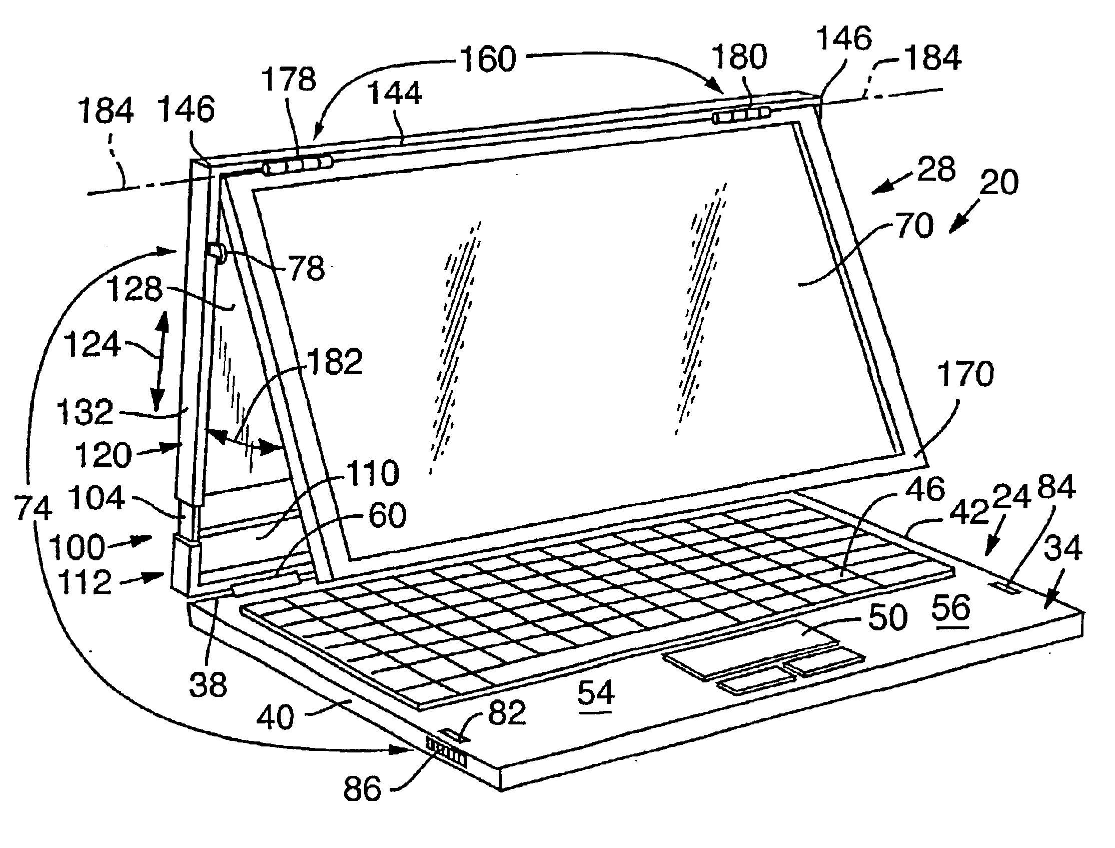
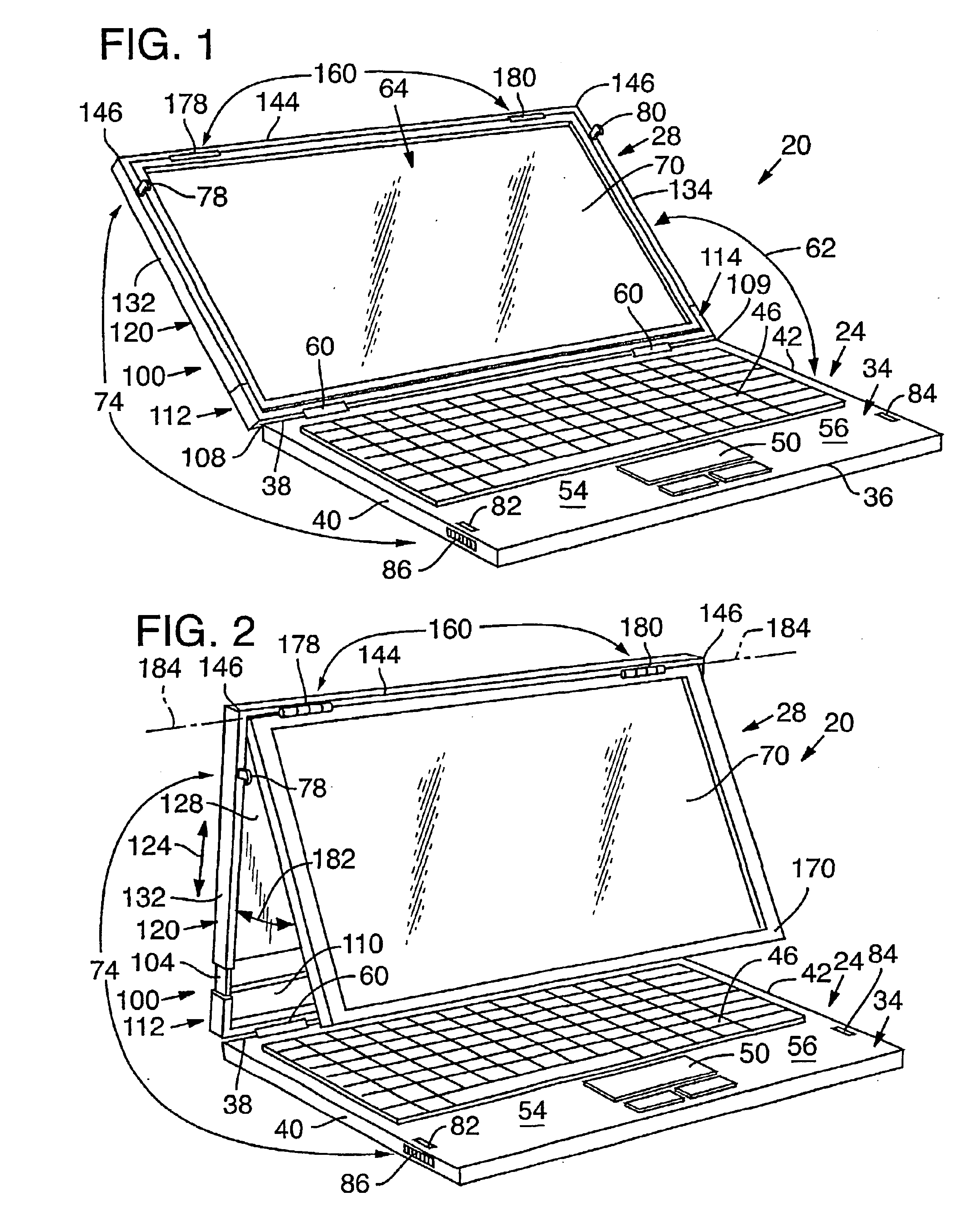
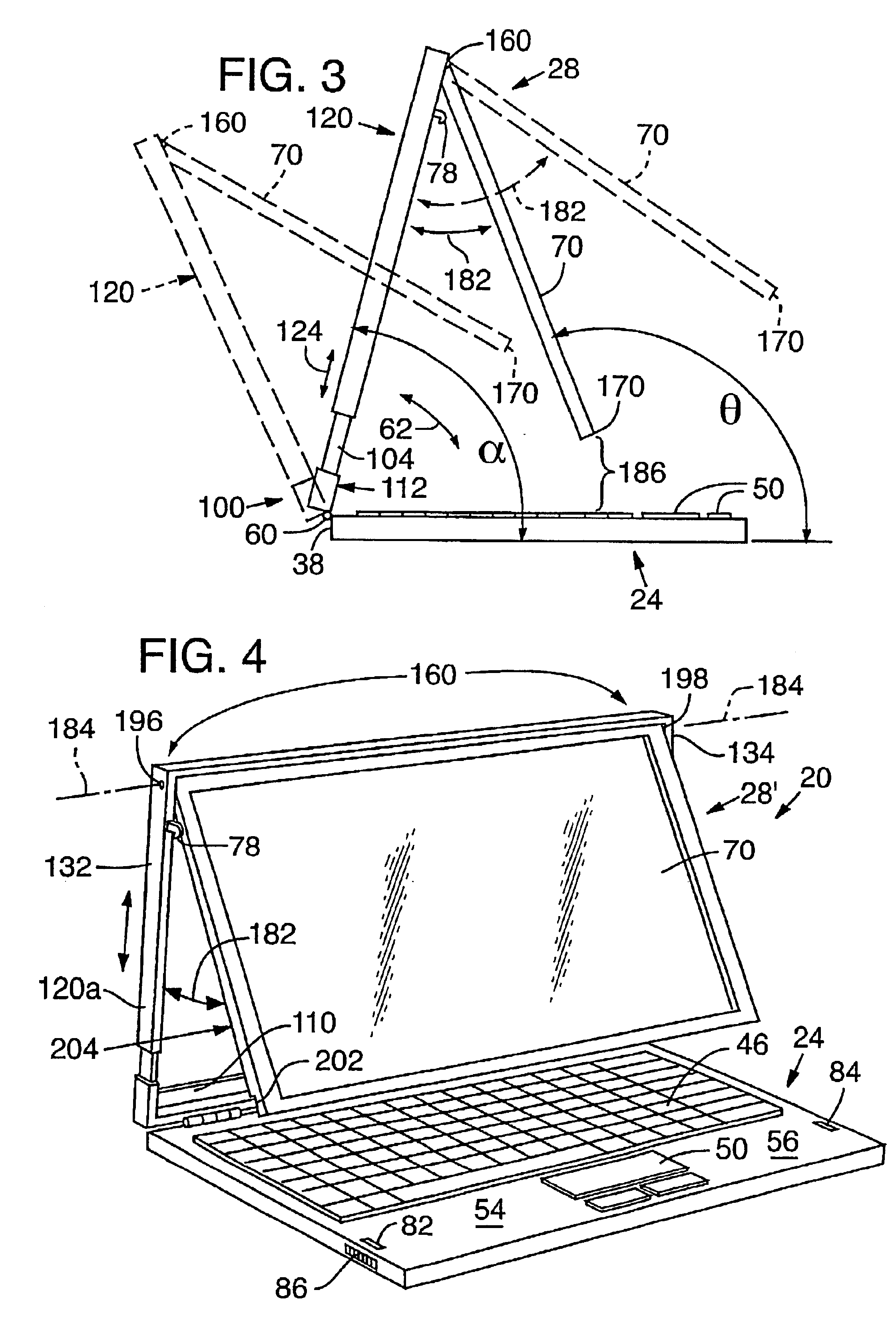
In accordance with the present invention, a computer display module is pivotally connected to a keyboard module of a laptop computer adjacent a rear margin of the keyboard module. The display module includes a rail assembly rotatably connected to the keyboard module at the rear margin and extending outwardly from the rear margin. A display support member of the display module is mounted to the rail assembly for sliding movement along the rail assembly upwardly from the keyboard module when the display module is rotated to an open position. An adjustable display panel of the display module is rotatably mounted to a top portion of the display support member at an articulating joint. The articulating joint is positioned adjacent a top margin of the display panel so that the display panel can be manually swung away from the display support member and toward a user of the laptop computer. The display support member is adjustable along the rail assembly to a height that provides sufficient clearance over the keyboard to allow the display panel to rotate about the articulating joint to a comfortable viewing angle without blocking access to the keyboard.

Problems solved by technology

Furthermore, when an airline passenger seat immediately in front of the user is reclined, it can be very difficult for the user to view the display.
Use in constrained spaces is especially problematic for laptop computer displays utilizing active matrix LCD technology, which is optically directional and has a limited useful viewing angle.
In the presentation position, however, the display screen blocks access to the keyboard of the laptop computer.
This fully extended position is not always desirable, for example, when using the laptop computer on a tall table.
Fully extending the display screen also raises the center of gravity of the laptop computer, thereby making it more prone to tipping.
Furthermore, placement of the keyboard at the front margin of the computer does not accommodate a pointing device, such as a touch pad or trackball, in front of the keyboard, as is done in many conventional laptop computers.

Method used


Image

  • Display mounting for laptop computer
  • Display mounting for laptop computer
  • Display mounting for laptop computer

Examples


Embodiment Construction

FIG. 1 is a perspective view of a laptop computer 20 including a keyboard module 24 pivotably connected to a display module 28 in accordance with a first preferred embodiment of the present invention. With reference to FIG. 1, keyboard module 24 is generally tabular in shape and is adapted for placement on a horizontal support surface, such as a user's lap or a table (not shown). Keyboard module 24 includes an upper face 34 bounded by front, rear, left, and right margins 36, 38, 40, and 42, respectively. A keypad 46 is positioned on upper face 34 of keyboard module 24 and adjacent rear margin 38. Keypad 46 may be a QWERTY keyboard of the type used in conventional laptop and notebook computers, or any other kind of keypad, pen tablet, or other manual computer input device. A pointing device 50, such as a touchpad mouse or trackball, for example, is also provided on upper face 34 of keyboard module 24, adjacent keypad 46 and proximal of front margin 36. Pointing device 50 is located m...


PUM


Abstract

A laptop computer display module (28) for use in a clamshell type laptop computer includes a telescoping rail assembly (100) that enables the display module (28) to be extended upwardly from a keyboard module (24) of the laptop computer when the display module is rotated to an open position. A computer display panel (28) is rotatably mounted to a display support member (120) of the display module adjacent a top margin of the display panel (70) so that the display panel (70) can be manually swung away from the display support member (120) and toward a user of the laptop computer (20). The invention enables the display panel (70) to be positioned at a comfortable viewing angle without blocking access to the keyboard module (24) for typing and is particularly useful in depth-constrained workspaces such as airplane passenger seats, where the display support member (120) must be positioned at an acute angle relative to the keyboard module (24).

Description

TECHNICAL FIELDThis invention relates to laptop computer display screens and, in particular, to a laptop computer having an improved clamshell type housing that facilitates adjustment of the display screen to a comfortable viewing angle.BACKGROUND OF THE INVENTIONConventional clamshell type laptop computers have an upper display unit rotatably connected to a main module that holds a processor unit, a keyboard, a pointing device, data storage devices, and other peripherals. A hinge positioned at a bottom margin of the display unit connects the display unit to the main module near a rear margin of the main module. Rotation of the display unit about the hinge determines the viewing angle of the display. In normal operation, the display unit is typically rotated to an obtuse angle relative to the keyboard. At a comfortable viewing angle, in which the display faces slightly upward, the display unit extends rearward, away from the main module and the hinge. Adjustment of the display unit ...

Claims


Application Information

Patent Timeline
Patent Type & Authority Patents(United States)
IPC IPC(8): G06F1/16
CPCG06F1/1616Y10T292/1025
Inventor IREDALE, RICHARD J.
Owner IREDALE RICHARD J
Learn More