System for dynamically controlling power provided by an engine

a technology of dynamic control and engine, applied in the direction of electrical control, process and machine control, etc., can solve the problems of limiting the driving mode to performance, limiting the process to transmission gear ratio applications, and limiting the control to predetermined performance curves and predetermined performance limits

Inactive Publication Date: 2005-01-11
CATERPILLAR INC
View PDF44 Cites 28 Cited by
  • Summary
  • Abstract
  • Description
  • Claims
  • Application Information

AI Technical Summary

Problems solved by technology

Although such electronic engine control systems allow power to an engine to be adjusted based on varying load conditions, the control is limited to predetermined performance curves and predetermined performance limits.
Although the dynamic control process taught by Speicher et al. allows a system to operate within a variable range, the process is limited to transmission gear ratio applications.
Further, Speicher et al. does not allow the upper and / or lower limits to be adjusted beyond their designed limits, thus limiting driving modes to performance ranges that are narrowly defined within these limits.
Additionally, during operations, engines may experience a momentary exposure to a loading condition that may warrant operations that may exceed maximum performance operating limits.
Although the engine control system described by Rodgers enables an engine to receive a momentary “torque burst,” the excess torque provided by the system is limited to starter systems and operations.

Method used


Image

  • System for dynamically controlling power provided by an engine
  • System for dynamically controlling power provided by an engine
  • System for dynamically controlling power provided by an engine

Examples


Embodiment Construction

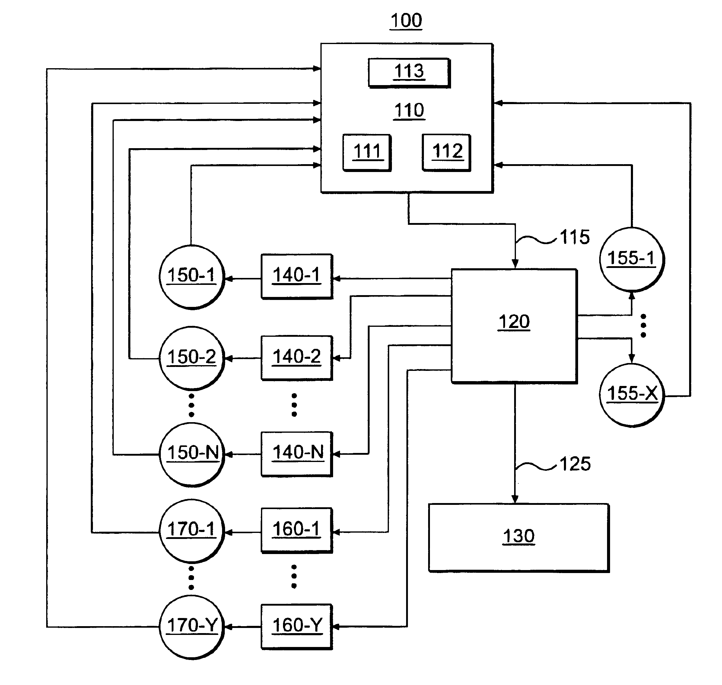
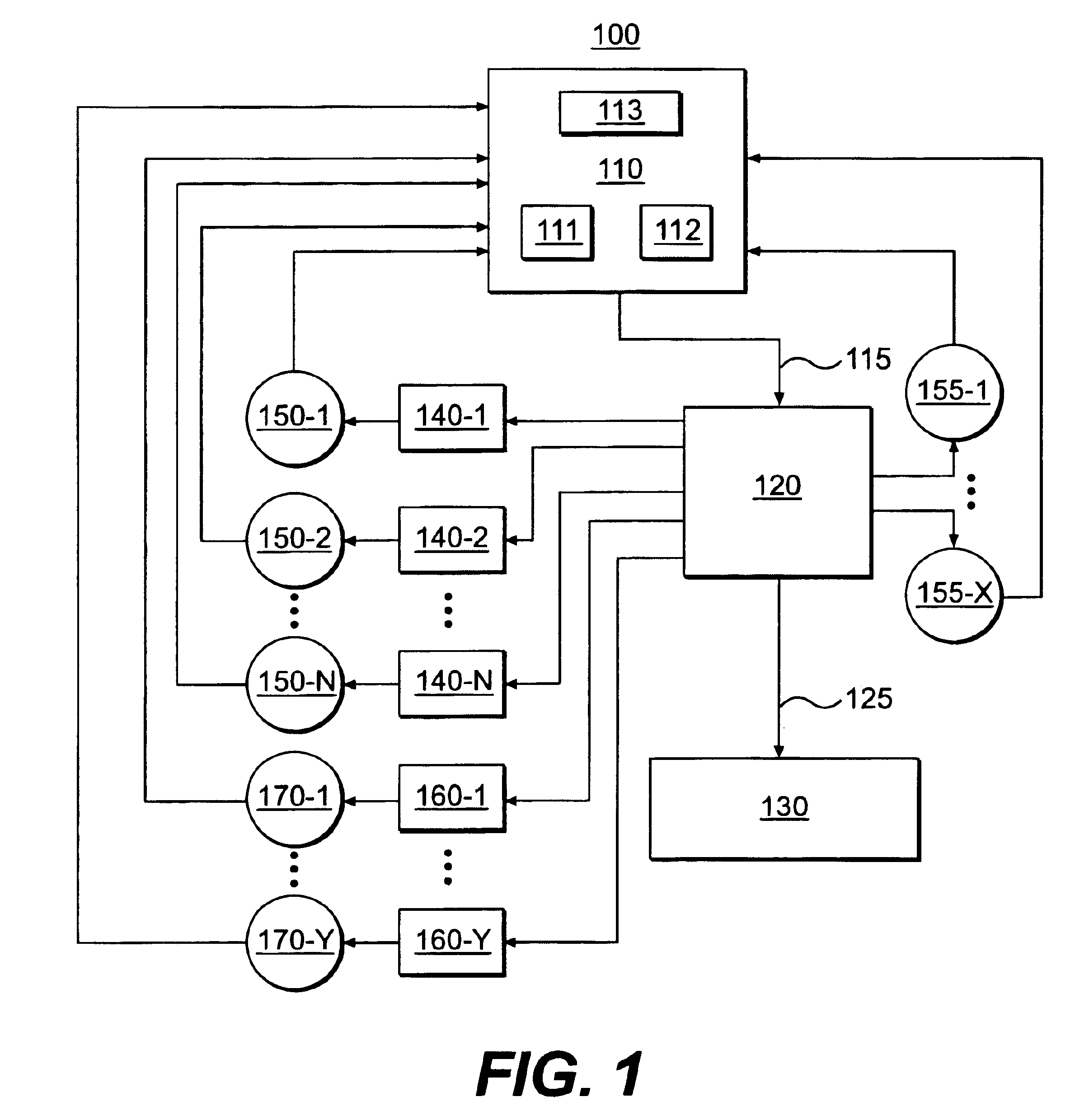
Reference will now be made in detail to the exemplary embodiments of the invention, examples of which are illustrated in the accompanying drawings. Wherever possible, the same reference numbers will be used throughout the drawings to refer to the same or like parts.

FIG. 1 illustrates an exemplary system 100 in which features and principles consistent with embodiments of the present invention may be implemented. In one embodiment of the invention, system 100 may be associated with any type of machine, such as a machine that includes a combustion type engine. For example, system 100 may affiliated with a marine vehicle, land vehicle, and / or an aircraft. Further, the vehicle may be exposed to particular work applications, such as a tractor with hydraulically controlled accessory components (e.g., front end loader). Alternatively, system 100 may be associated with non-vehicle machines, such as a machine that includes an engine that drives manufacturing equipment in a manufacturing plant...


PUM


Abstract

A method and system may be provided to perform a process for controlling power provided by an engine in a machine. In an embodiment of the present invention, a process for controlling power provided by an engine operating in a machine is provided. The process may include determining a first power value reflecting a predetermined first power to be provided by the engine to a component operating in the machine and determining, during machine operations, at least one of a parasitic load power value and an intermittent power load value. A second power value may then be determined that reflects a second power provided by the engine based on the parasitic power value, the intermittent power value, and the net power value. The second power value is adjusted such that the engine substantially provides the predetermined net power to the component.

Description

TECHNICAL FIELDThis invention relates generally to engine control systems, and more particularly to methods and systems for dynamically controlling engine power based on parasitic and / or intermittent loads.BACKGROUNDEngines are typically designed according to operating limits associated with certain component attributes. For example, certain engine specifications, such as fuel injection timing, fluid pump design, cooling system capabilities, etc., of an engine may be designed with operating limits corresponding to various parameters, such as engine speed and torque. The relationship between an engine's operating limits and selected operating parameters are sometimes represented as software-based performance maps that an engine controller may access to provide control signals to an engine to ensure the engine operates within the boundaries reflected by the operating limits.A performance map for a particular engine may include several different performance curves based on varying load...

Claims


Application Information

Patent Timeline
Patent Type & Authority Patents(United States)
IPC IPC(8): F02D41/02
CPCF02D41/021Y10T477/65
Inventor ANDRES, DAVID J.RIEDIGER, CRAIG W.WILSON, DONALD E.TIMMONS, JOHN P.LORENTZ, TIMOTHY A.
Owner CATERPILLAR INC
Why Eureka
Try Eureka