
Apparatus, method and computer program product for converting simple locks in a multiprocessor system

a multi-processor system and lock technology, applied in the field of apparatus, method and computer program product for converting simple locks, can solve the problems of increasing the potential for contention for a lock that protects a shared memory resource, the entire smp system, or node, going down, etc., and avoiding the extra overhead of krlocks. , the effect of avoiding starvation

Inactive Publication Date: 2005-01-11
IBM CORP
View PDF6 Cites 23 Cited by
  • Summary
  • Abstract
  • Description
  • Claims
  • Application Information

AI Technical Summary

Benefits of technology

The present invention provides an apparatus, method and computer program product for minimizing the negative effects that occur when simple locks are highly contended among processors which may or may not have identical latencies to the memory that represents a given lock. The present invention minimizes these effects through an improved apparatus, method and computer program product for converting simple locks.
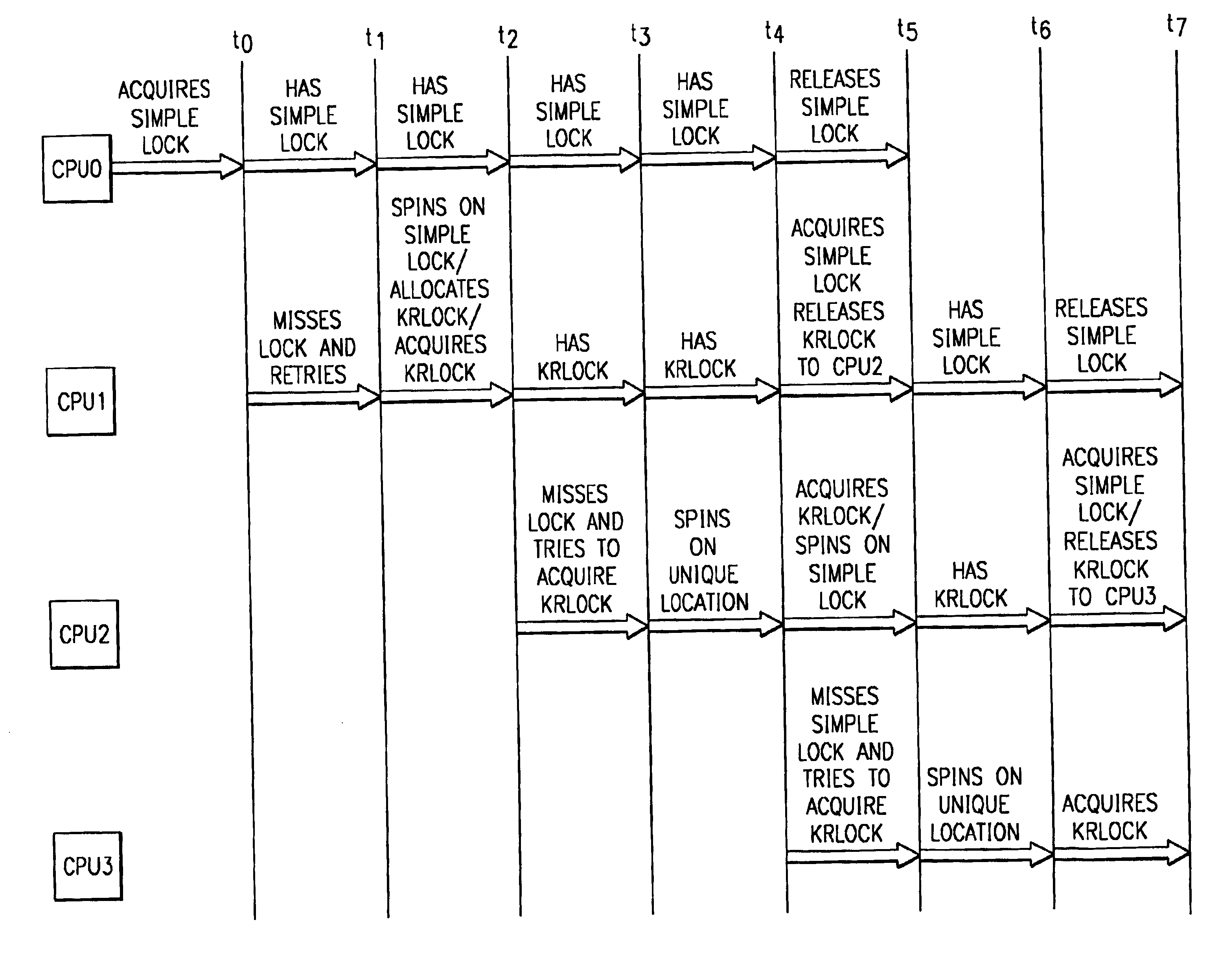
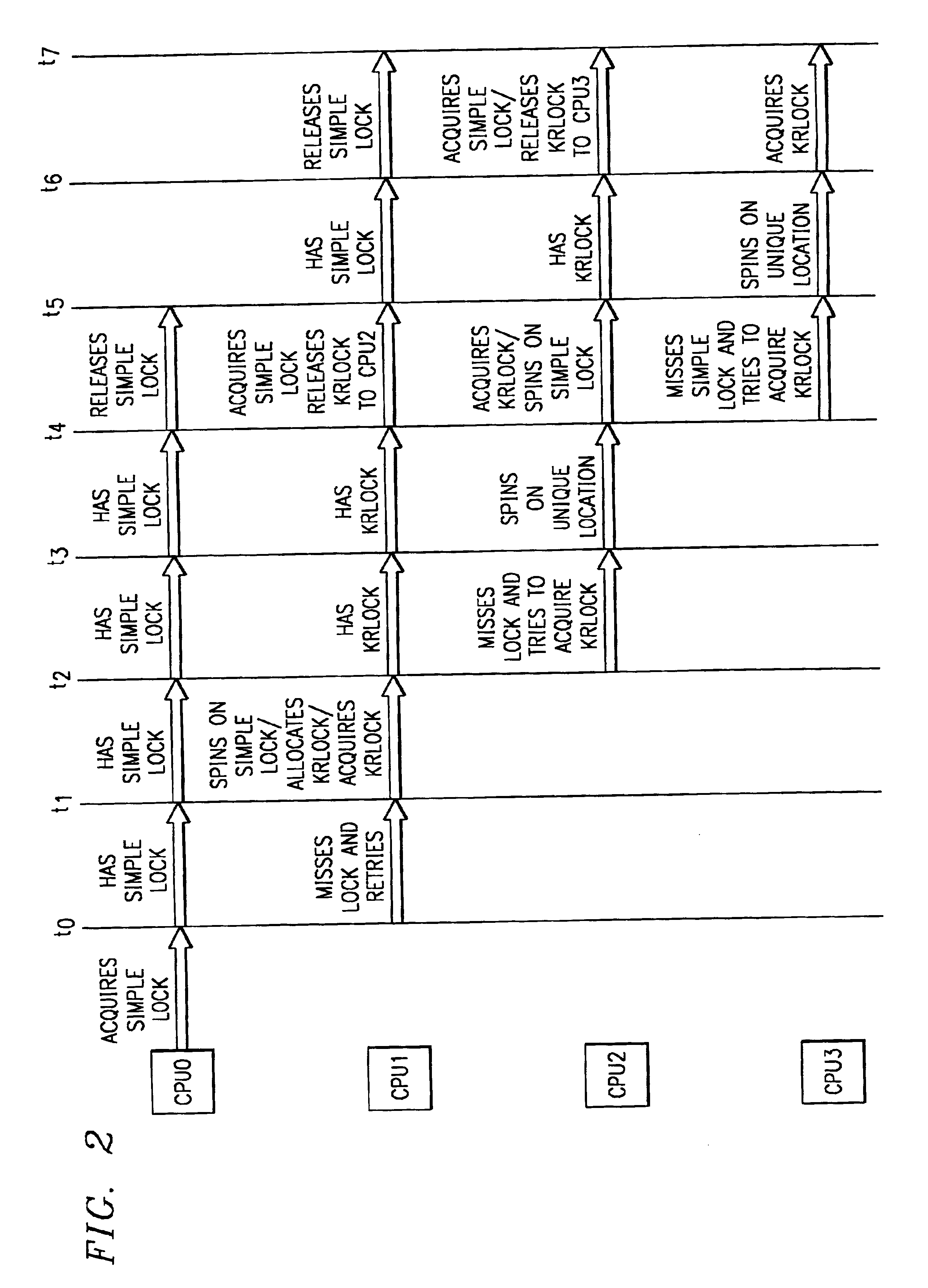
In the present invention, to achieve fairness for each of the processors in the multiprocessor system, more structure is added to the locking mechanism. Within the mutex lock mechanism simple_lock( ) framework, krlocks are used to control simple lock acquisition. Where other mutex lock mechanisms like simple_lock( ) ‘spin’ on the lock word to acquire the mutex, the present invention requires the acquisition of a krlock (which is exclusive and fair) before ‘spinning’ on the simple lock mutex.
When a thread releases a krlock, the unlocking code changes the value of the spin location of the requesting processor to which the krlock is being granted. That processor holds the krlock until it grants the krlock to the next processor. If no processor holds the krlock, it is granted immediately. If no processor is requesting the krlock at krlock release time, it is not held by any processor and is available to be granted immediately. Since the krlock is pushed to the next processor instead of pulled to the processor with the smallest latency, the mechanism avoids starvation and is thus more fair.
Within the krlock framework, processors with identical latencies are grouped together and a krlock is granted within that group as a matter of bias. After handing off to the same group for some set number of hand-offs (or until no other processor within the group is requesting the krlock), the krlock is passed to a different set of processors that have equal latencies with respect to one another, but potentially different latencies with respect to the previous group. Since krlocks occur under the framework of the simple lock mechanism, the effect is that simple locks, when contended, behave the same way that krlocks behave, without requiring any changes in the binary interface to simple_lock( ).
The benefit of the present invention is that when the simple locks aren't contented (which they shouldn't normally be), the extra overhead of the krlock is avoided. When simple locks are contended, they now act fairly and work in the face of differing latencies between all the processors involved. Thus, the present invention provides a significant functional benefit as well as a ‘compatibility’ with existing source and binary code that uses the simple_lock( ) interface.

Problems solved by technology

SMP systems, however, are fallible in that if one processor fails, the entire SMP system, or node, goes down.
As the number of processors in a system increases, the potential for contention for a lock that protects a shared memory resource increases dramatically.
In NUMA systems, processors that access a memory location (or mutex) will have different latencies, with the effect being that acquisition of the lock by a processor with a longer latency will be more difficult than by a processor with a shorter latency.
This makes normal mutex lock acquisition unfair.
A given processor that has a longer latency to a mutex than other processors has a disadvantage with respect to all those other processors.
When latencies can be different, a given processor or a number of processors may become unable to acquire a lock due to starvation from processors with shorter latencies.

Method used


Image

  • Apparatus, method and computer program product for converting simple locks in a multiprocessor system
  • Apparatus, method and computer program product for converting simple locks in a multiprocessor system
  • Apparatus, method and computer program product for converting simple locks in a multiprocessor system

Examples


Embodiment Construction

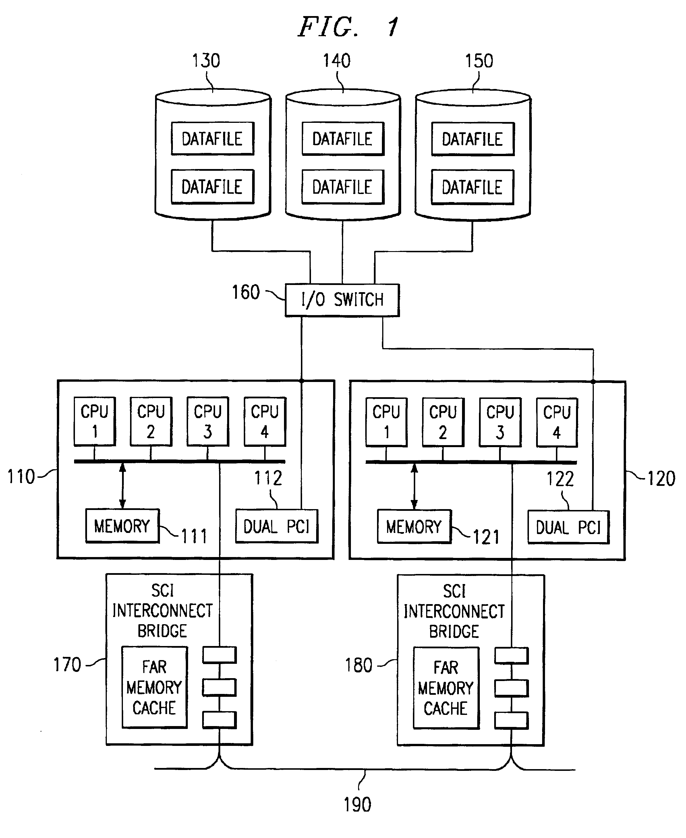
With reference now to the figures, FIG. 1 is an exemplary block diagram of a multiprocessor system in accordance with the present invention. The particular example multiprocessor system 100 shown in FIG. 1 is a non-uniform memory access (NUMA) multiprocessor system, however, other types of multiprocessor systems may be used without departing from the spirit and scope of the present invention. The multiprocessor system 100 is only intended to be exemplary of the multiprocessor systems in which the present invention may be incorporated and is not intended to place any architectural limitations on the present invention.

As shown in FIG. 1, the NUMA multiprocessor system 100 includes a plurality of nodes 110 and 120 shared system resources 130-150, and an input / output (I / O) switch 160. The I / O switch 160 is a mechanism for providing pathways to the shared system resources 130-150 for the various nodes 110 and 130 of the multiprocessor system 100.

Each node 110 and 120 includes a plurality...


PUM


Abstract

An apparatus, method and computer program product for minimizing the negative effects that occur when simple locks are highly contended among processors which may or may not have identical latencies to the memory that represents a given lock, are provided. The apparatus, method and computer program product minimize these effects by converting simple locks such that they act as standard simple locks when there is no contention and act as krlocks when there is contention for a lock. In this way, the number of processors spinning on a lock is limited to a single processor, thereby reducing the number of processors that are in a wait state and not performing any useful work.

Description

BACKGROUND OF THE INVENTION1. Technical FieldThe present invention is directed to an apparatus, method and computer program product for converting simple locks (e.g., disabled mutex spin locks) in a multiprocessor system. More specifically, the present invention is directed to an apparatus, method and computer program product for minimizing the negative effects that occur when such locks are highly contended among processors which may or may not have identical latencies to the memory that represents a given lock.2. Description of Related ArtMultiprocessing systems provide the benefits of being able to process multiple instructions simultaneously. Such systems have increased the number of instructions per cycle that computer systems are able to execute and have added to the speed at which computerized functions are performed.One type of multiprocessing system is the Symmetric Multiprocessing (SMP) system. The SMP architecture is an architecture in which multiple processors share the ...

Claims


Application Information

Patent Timeline
Patent Type & Authority Patents(United States)
IPC IPC(8): G06F9/46
CPCG06F9/524
Inventor BROWNING, LUKE MATTHEWMATHEWS, THOMAS STANLEYMCKENNEY, PAUL EDWARDMOODY, JAMES BERNARD
Owner IBM CORP
Learn More