Pivoting instrument panel central stack structure and method for flow-through instrument panel console interface

a central stack structure and instrument panel technology, applied in monocoque constructions, roofs, transportation and packaging, etc., can solve the problems of high cost, uneven gaps between adjacent fixed portions of the instrument panel and the console, and complicating the flow-through goal, so as to improve the adjustment of the shifter face plate assembly and the effect of high quality and low cos

Inactive Publication Date: 2005-01-18
GM GLOBAL TECH OPERATIONS LLC
View PDF10 Cites 47 Cited by
  • Summary
  • Abstract
  • Description
  • Claims
  • Application Information

AI Technical Summary

Benefits of technology

A central stack trim plate is affixed to the central stack modular structure for unitary movement therewith. The trim plate has two parallel surfaces on the sides to interface with the glove box door and the driver's side knee bolster. This relationship between the respective trim plate portions and the inboard edges of the glove box and bolster forms slip planes which hide angle variations when the central stack structure pivots, thereby maintaining a constant gap.
The brackets provide a low cost program specific structure which brings the pivot axis behind a cross car instrument panel feature line which is part of the design theme. This makes any horizontal gap aesthetically unchangeable and unnoticeable due to pivoting the unitary central stack and floor console to accommodate the variation in floor build.
Another feature combinable with the pivotable unitary central stack structure and floor console is an improved adjustable or horizontally floatable shifter face plate assembly which also accommodates variations between console and vehicle floor due to floor build variations during vehicle assembly. The result is also high quality fits and a world class modern look. The improvement of this feature also eliminates the need for an escutcheon or ring around the shifter face plate to hide any uneven gaps between the shifter face plate assembly and the shifter rod opening in the floor console.
The adjustable shifter face plate assembly is improved by permitting the face plates to float horizontally. This also accommodates the floor build variations. There is an intermediary plate which carries the shifter position marks or indicia (PRNDL) and which is movable sidewise to close any lateral gaps between the shifter plate assembly and the console opening. The intermediary plate also has an anti-rattle feature. The top plate can move longitudinally to close any longitudinal gaps between the shifter plate assembly and the console opening. An eccentric cone is movably positioned on the shifter rod. The cone can be pushed down on the shifter rod shaft after the intermediary plate and the top plate have found their right positions on the console base to cover the shifter rod opening. The eccentricity of the cone is used to accommodate any lateral shift in the parts occasioned by any floor build variations and the float of the intermediary and top plates. The cone can be twisted or rotated on the shifter to achieve the world class look desired between the shifter rod and the shifter face plate assembly.

Problems solved by technology

In the prior art, engineering faced continuing challenges to achieve design goals when seeking a “flow-through” (i.e., the appearance of uninterrupted connection) between the instrument panel and the floor console.
The mass assembly of vehicles necessarily have build variations that complicate this flow-through goal.
Attempts to achieve a smooth flow-through between instrument panel and floor console may result in uneven gaps between adjacent fixed portions of the instrument panel and the console.
Past attempts to achieve such results have been to reduce the build variations of the metal body, but this results in higher costs.

Method used


Image

  • Pivoting instrument panel central stack structure and method for flow-through instrument panel console interface
  • Pivoting instrument panel central stack structure and method for flow-through instrument panel console interface
  • Pivoting instrument panel central stack structure and method for flow-through instrument panel console interface

Examples


Embodiment Construction

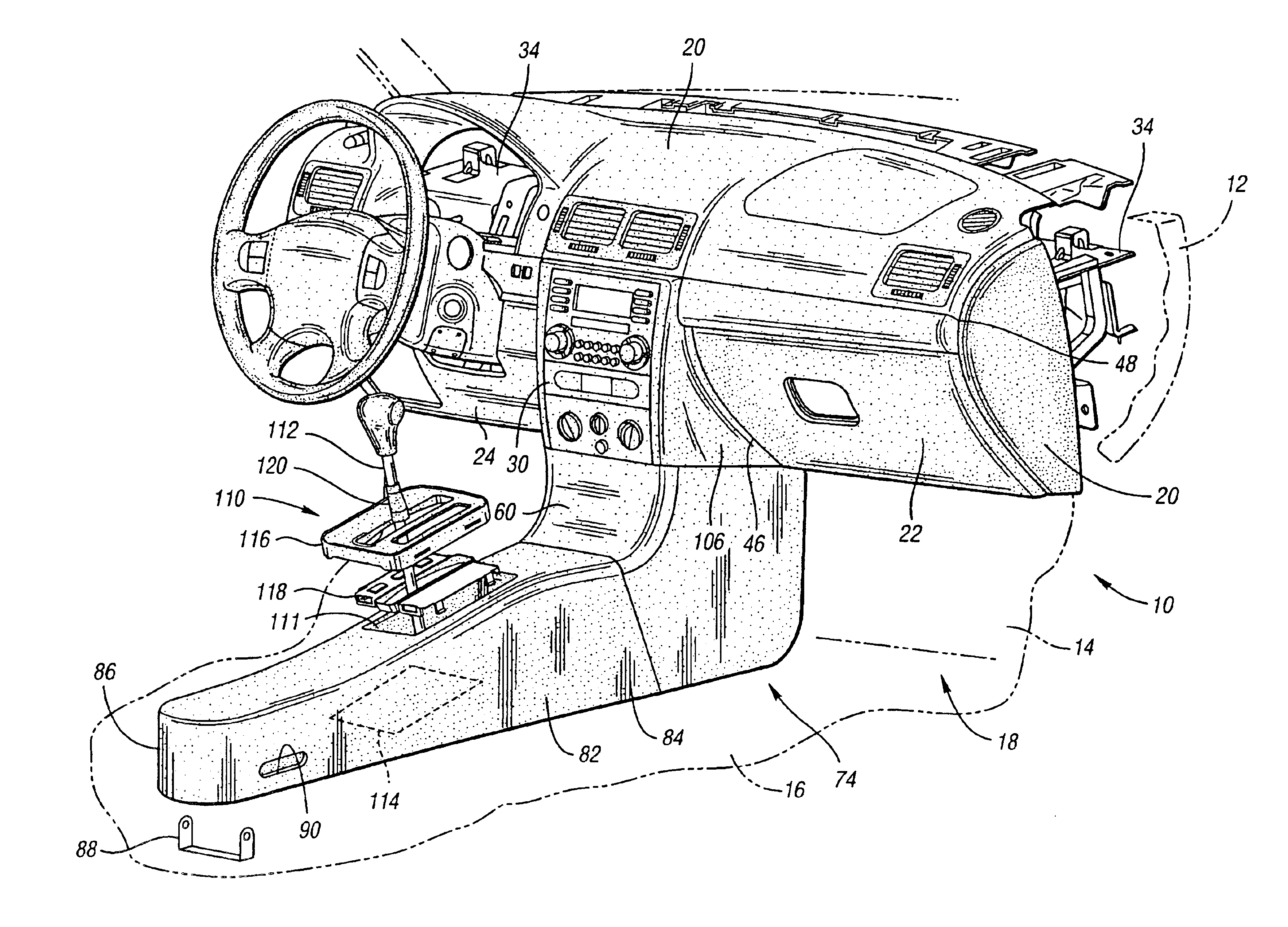
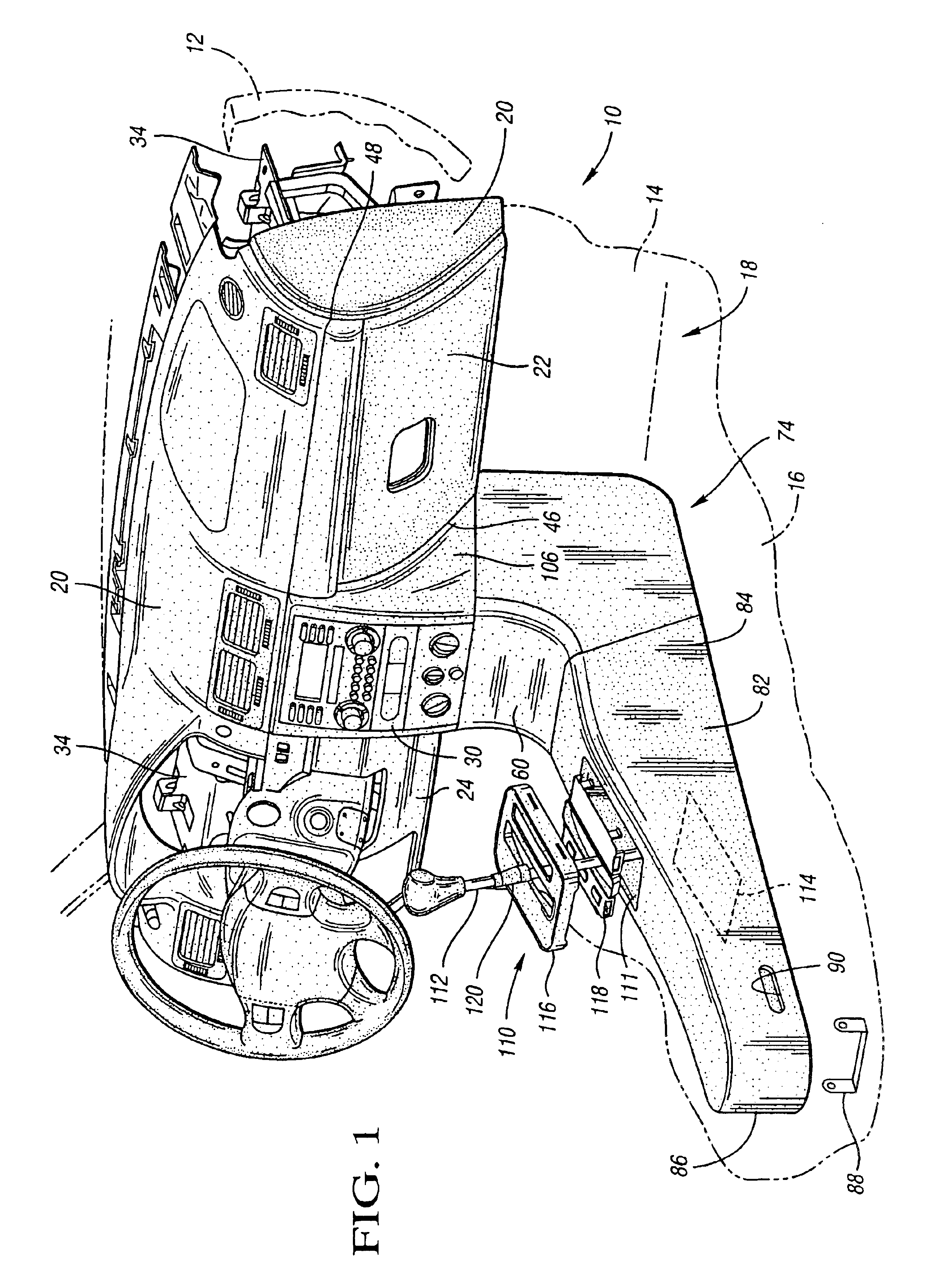
This is an invention to improve the fit of an instrument panel and console to an automotive vehicle built by mass assembly. With reference to FIG. 1, the vehicle 10 includes a structural frame 12, a front wall 14, and a floor 16. During mass production, the orientation of the frame 12 and the vehicle floor 16 may vary between vehicles being assembled. A passenger compartment 18 in such vehicles is defined by front wall 14 and floor 16. Thus, the location of floor 16 with respect to frame 12 may vary. Across the front of the passenger compartment is a vehicle instrument panel (IP) 20. The instrument panel 20 includes a fixed or stationary glove box panel or door portion 22 and a fixed or stationary driver's side knee bolster panel portion 24. A vehicle option package 30 rests between the glove box panel and the knee bolster.

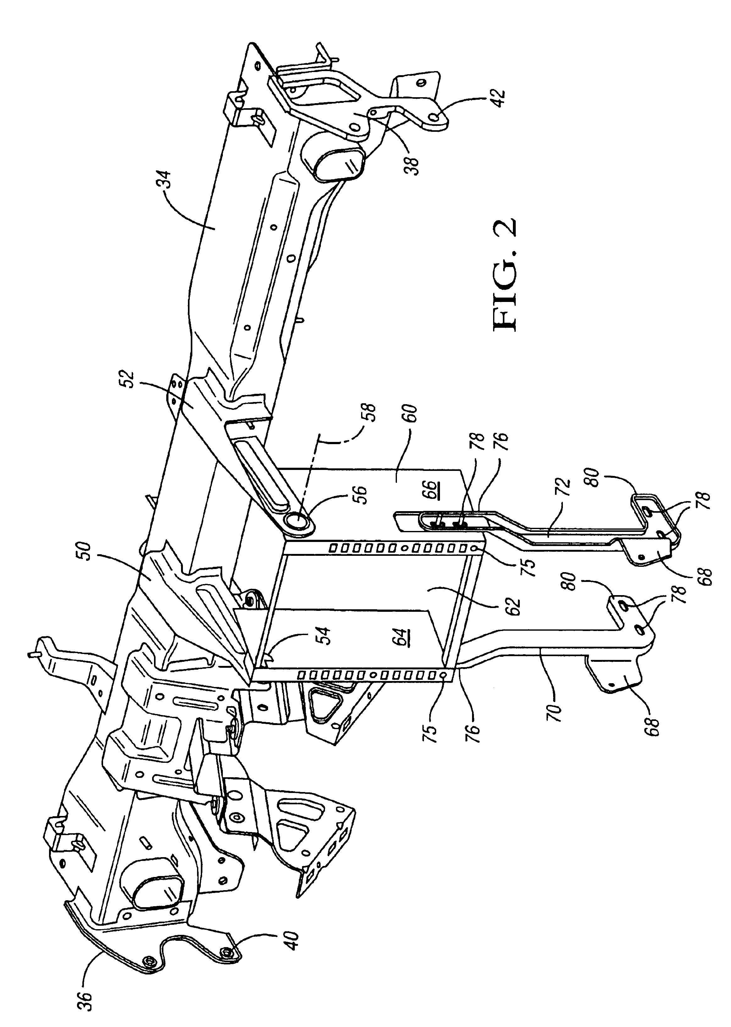
Turning now to FIG. 2, the instrument panel includes an instrument panel beam 34 having ends 36, 38 which affix to the frame 12 (FIG. 1) on opposite sides of the ...


PUM


Abstract

An adjustable instrument panel for a mass assembled vehicle includes a transverse upper support beam which is generally fixed with respect to the vehicle during assembly. A central stack modular structure is pivotably suspended from the upper support beam and adapted to house one or more vehicle options such as a radio, CD, and air conditioning control. The central stack modular structure is combined with a floor console as a unitary structure which has a lower support brace to adjustably connect the unitary structure with respect to the vehicle floor so that the instrument panel can accommodate floor build variations and obtain flow-through with the floor console in vehicles being mass assembled.

Description

TECHNICAL FIELDThis invention relates to a flow-through instrument panel for a vehicle to accommodate floor build variations in vehicle assembly.BACKGROUND OF THE INVENTIONIn the prior art, engineering faced continuing challenges to achieve design goals when seeking a “flow-through” (i.e., the appearance of uninterrupted connection) between the instrument panel and the floor console. The mass assembly of vehicles necessarily have build variations that complicate this flow-through goal. Attempts to achieve a smooth flow-through between instrument panel and floor console may result in uneven gaps between adjacent fixed portions of the instrument panel and the console. The prior art lacks an improvement which would eliminate overhangs or shingling at these locations so that high quality fits of world class modern look can be achieved. Another need in the prior art is for a reduction in the number of floor console parts in a flow-through instrument panel. Past attempts to achieve such r...

Claims


Application Information

Patent Timeline
Patent Type & Authority Patents(United States)
IPC IPC(8): B62D25/14
CPCB62D25/145
Inventor OANA, ADRIAN
Owner GM GLOBAL TECH OPERATIONS LLC
Why Eureka
Try Eureka