Three-dimensional image projection employing retro-reflective screens

a three-dimensional image and retro-reflective technology, applied in projectors, instruments, stereoscopic photography, etc., can solve the problems of complex three-dimensional image technology, holographic imaging technology, and lack of real three-dimensional image provided by recreation, and achieve high resolution

Inactive Publication Date: 2005-01-18
VIRRILLI JAMES
View PDF19 Cites 55 Cited by
  • Summary
  • Abstract
  • Description
  • Claims
  • Application Information

AI Technical Summary

Benefits of technology

Similarly, it is an object of the present invention to provide apparatuses and associated methods for multi-aspect three-dimensional imaging that provides high resolution images without having to limit the viewer to restricted viewing zones.
Also, it is an object of the present invention to provide apparatuses and associated methods for multi-aspect three-dimensional imaging that can simultaneously provide different views to different viewers located at different viewing locations relative to one another.
Additionally, it is an object of the present invention that such apparatuses and the associated methods do not require the viewer to utilize specialized viewing equipment, such as headgear or eyeglasses.
Further, it is an object of the present invention to provide three-dimensional displays and related imaging methods that can display various images and perspectives of an object using image pairs which have been calculated to produce a perceived three-dimensional image when simultaneously projected for viewing.
To achieve these and other objects, three-dimensional projection systems and related methods according to the invention employ at least two projectors, an imaging system that controls the projectors, and a retro-reflective screen upon which is projected multiple images of an object as created by the projectors. The imaging systems of the projection systems according to embodiments of the present invention are capable of numerically calculating image information and using that information to control the characteristics of the projectors to produce stereo images. In embodiments of the invention wherein the projectors have liquid crystal imaging display elements incorporated therein, the imaging system is adapted to control the liquid crystal display elements within the projectors to modify the images being projected. The calculated image information relates to a desired three-dimensional image scene. The calculated image information in such embodiments causes the liquid crystal displays to be controlled in such a manner that a desired image is produced thereon, and light passes through the display and hits the screen where it is diffused or reflected according to the characteristics of the screen to produce a viewable three-dimensional image.

Problems solved by technology

Holographic imaging technologies, while being superior to traditional stereoscopic-based technologies in that a true three-dimensional image is provided by recreating the actual wavefront of light reflecting off a the three-dimensional object, are more complex than other three-dimensional imaging technologies.
This approach, however, imposes increasingly large bandwidth requirements on image processing equipment.
As the images become more complex, this prior art embodying this approach has proven less and less successful.
This is a difficult task that has not been mastered in the prior art.

Method used


Image

  • Three-dimensional image projection employing retro-reflective screens
  • Three-dimensional image projection employing retro-reflective screens
  • Three-dimensional image projection employing retro-reflective screens

Examples


Embodiment Construction

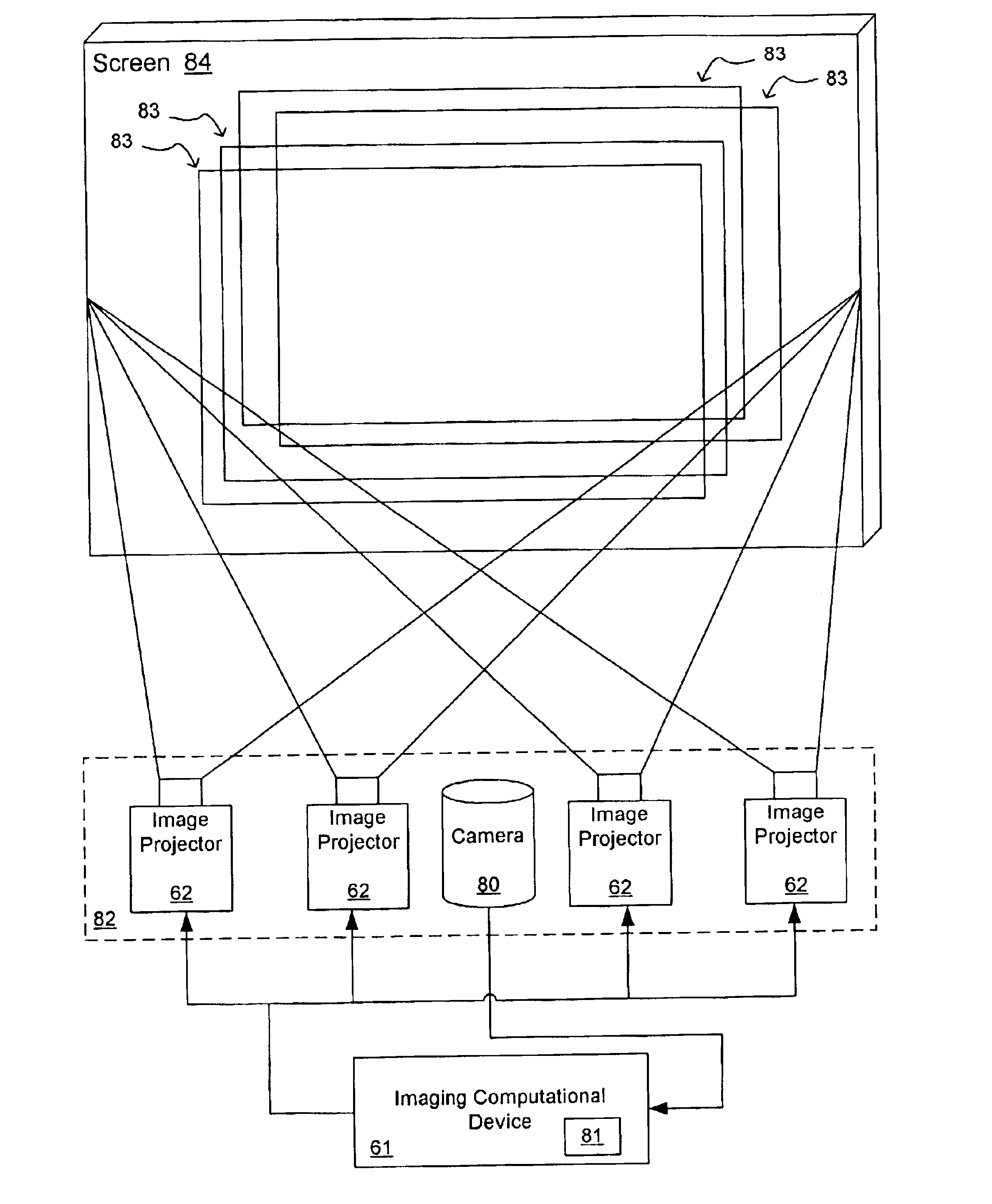
The present invention in its preferred embodiment is an image projection system and related method for presentation of multiple aspects of an image to create a three dimensional viewing experience using at least two image projectors, an image generation system for controlling the image projectors, and a retro-reflective screen.

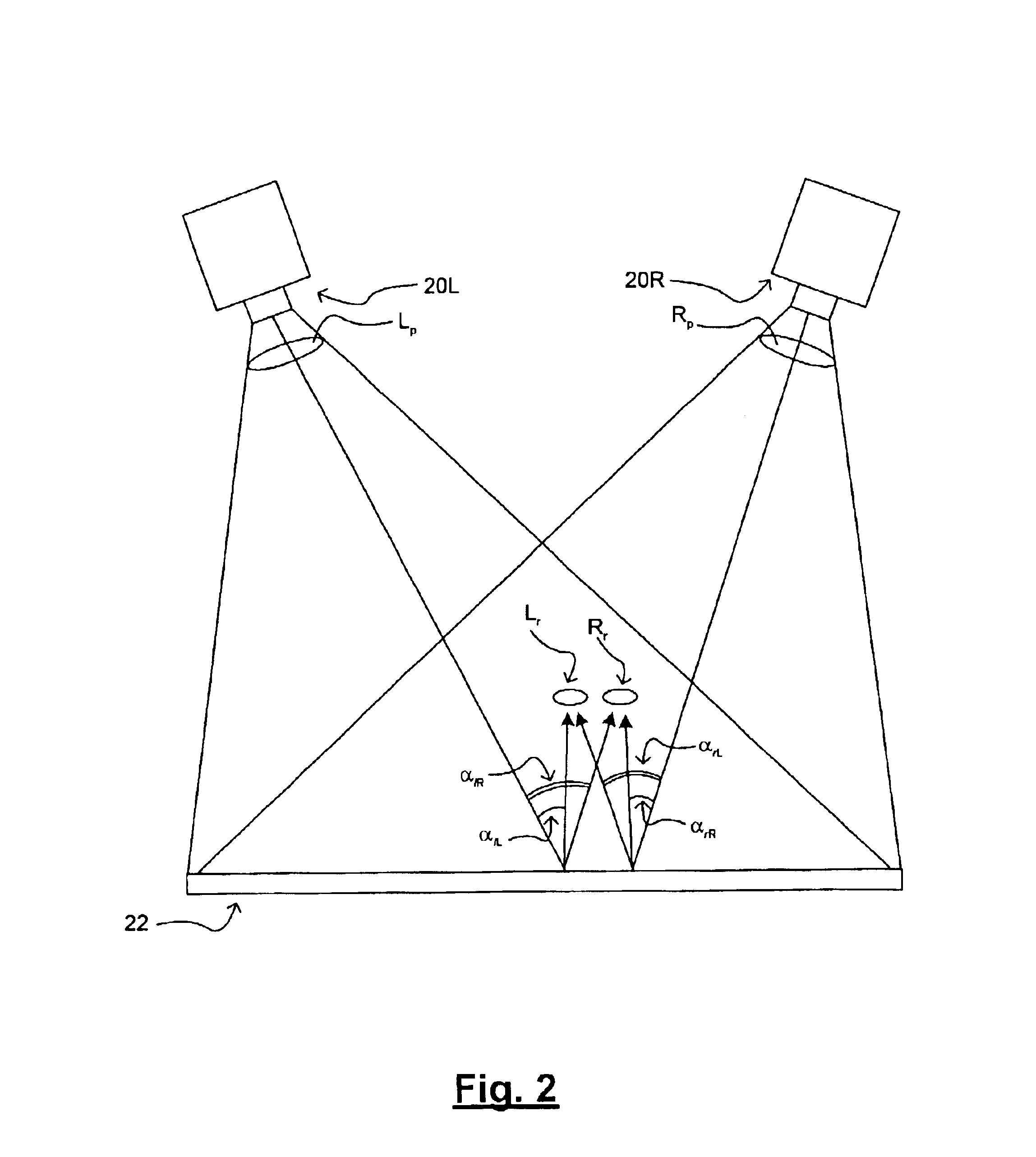
FIG. 2 schematically depicts the projection of three-dimensional images according to one embodiment of the present invention. As illustrated in FIG. 2, a three-dimensional or stereographic image is presented to a viewer using at least two projectors 20L and 20R to project calculated image Lp and calculated image Rp, respectively, such as from respective transmissive LCDs or other similar pixel-based displays, onto the retro-reflective screen 22 to present appropriate retro-reflected images Lr and Rr to the viewer's left and right eyes.

In embodiments of the invention, the retro-reflective screen 22 reflects light according to a non-linear distribution pattern t...


PUM


Abstract

Disclosed herein are three-dimensional projection systems and related methods employing two electronically controlled projectors and a retro-reflective screen. The retro-reflective screen produces a known non-linear light reflection pattern when images are projected thereon. Image computational means are used to calculating flat image information for each projector based upon inputted stereopair images and information regarding the projectors and screen. In preferred embodiments of the present invention, the projection system uses an image computational device that employs a neural network feedback calculation to calculate the appropriate flat image information and appropriate images to be projected on the screen by the projectors at any given time. More than two projectors can be employed to produce multiple aspect views, to support multiple viewers, and the like. In another embodiment, the projection system includes a digital camera that provides feedback data to the image computational device.

Description

FIELD OF THE INVENTIONThe present invention relates to the projection of three-dimensional images. More particularly, the present invention relates to apparatuses and related methods for three-dimensional image projection utilizing stereo aspect images projected onto a retro-reflective screen.BACKGROUND OF THE INVENTIONProjective displays use images focused onto a diffuser to present an image to a user. The projection may be done from the same side of the diffuser as the user, as in the case of cinema projectors, or from the opposite side. Prior art projection systems of the retro-reflective screen type used in, for example, movie theaters, as depicted in FIG. 1, typically produce a two-dimensional image by using a single projector 10 to project a single image at a time onto a screen 12. Screen 12 would have a linear light distribution such that all viewers of the image reflected by screen 12 would see the same two-dimensional image regardless of the positions at which they are loca...

Claims


Application Information

Patent Timeline
Patent Type & Authority Patents(United States)
IPC IPC(8): H04N13/00G03B35/20G03B21/00G03B21/10H04N13/349
CPCH04N13/0497H04N13/0278H04N13/0418H04N13/0425H04N13/0459H04N13/0475H04N13/0477H04N13/0481H04N13/0055H04N13/0289H04N13/0296H04N13/0422H04N13/0434H04N13/044H04N13/0445H04N13/047H04N13/0493H04N13/0495H04N13/0059H04N13/337H04N13/289H04N13/395H04N13/32H04N13/344H04N13/194H04N13/279H04N13/189H04N13/376H04N13/324H04N13/393H04N13/368H04N13/38H04N13/296H04N13/349H04N13/363H04N13/373H04N13/327H04N13/398H04N13/00
Inventor PUTILIN, ANDREY N.LUKYANITSA, ANDREW A.
Owner VIRRILLI JAMES
Why Eureka
Try Eureka