Multi-sub band concurrent MIMO-SAR radar imaging method

A MIMO-SAR and radar imaging technology, applied in radio wave reflection/re-radiation, using re-radiation, measurement devices, etc., can solve the problem of affecting the imaging quality of MIMO-SAR radar, the inconsistency of amplitude and phase at the receiving end of MIMO-SAR radar, etc. question

Active Publication Date: 2017-01-18
XIDIAN UNIV
View PDF5 Cites 14 Cited by
  • Summary
  • Abstract
  • Description
  • Claims
  • Application Information

AI Technical Summary

Problems solved by technology

However, in the actual MIMO-SAR radar experiment, due to the inevitable existence of various errors in the MIMO-SAR radar hardware, as well as the influence of the movement error of the flying experiment, the MIMO-SAR radar receiving end receives the same amplitude of each sub-band signal. Inconsistency, thus affecting the imaging quality of MIMO-SAR radar

Method used


Image

  • Multi-sub band concurrent MIMO-SAR radar imaging method
  • Multi-sub band concurrent MIMO-SAR radar imaging method
  • Multi-sub band concurrent MIMO-SAR radar imaging method

Examples


Embodiment Construction

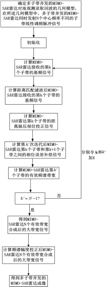
[0033] refer to figure 1 , is a flow chart of a multi-subband concurrent MIMO-SAR radar imaging method of the present invention; the multisubband concurrent MIMO-SAR radar imaging method comprises the following steps:

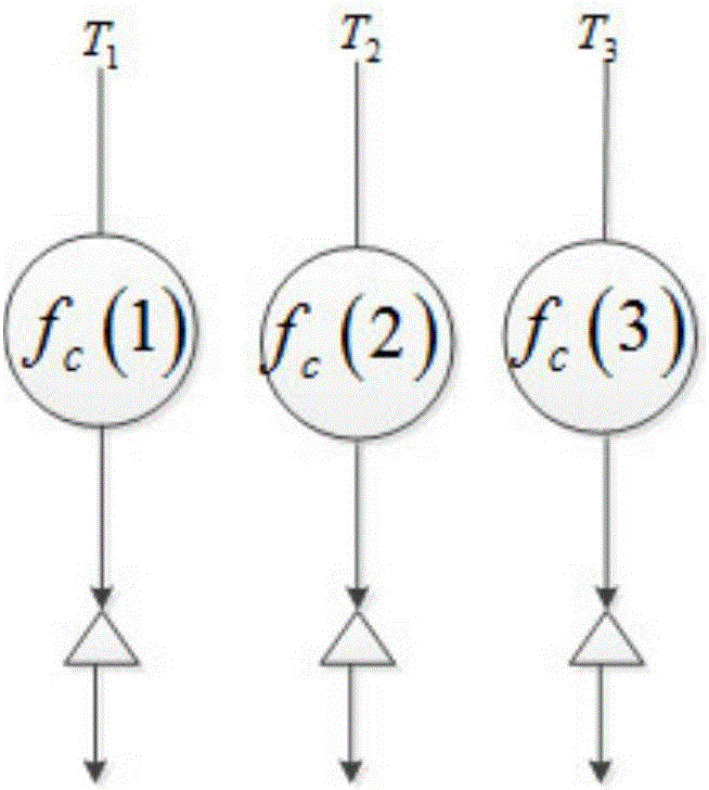
[0034] Step 1, determine the geometric model of the earth observation acquisition echo of the multi-subband concurrent MIMO-SAR radar. In the geometric model, the multi-subband concurrent MIMO-SAR radar simultaneously transmits N center frequencies (carrier frequencies) with different The sub-band chirp signal of , the bandwidth of each sub-band chirp signal is B 0 , the pulse length of each sub-band chirp signal is T 0 ; Multi-subband concurrent MIMO-SAR radar includes N subbands, wherein the frequency interval (frequency step) between adjacent subbands is f step ; N is an odd number greater than 0.

[0035] Specifically, determine the geometric model of the multi-subband concurrent MIMO-SAR radar's earth observation acquisition echo. In the geometric model...


PUM


Abstract

The invention discloses a multi-sub band concurrent MIMO-SAR radar imaging method mainly comprising the following steps: determining a geometrical model of earth observation recording echo of multi-sub band concurrent MIMO-SAR radar; calculating the baseband signal of a kth sub band received by MIMO-SAR radar and the baseband signal of the kth sub band received by the MIMO-SAR radar after range matching filtering; calculating the effective spectrum bandwidth of a k'th sub band of the MIMO-SAR radar; calculating a large-bandwidth signal S generated through synthesis of N effective spectrum bandwidths of the MIMO-SAR radar; correcting the spectrum amplitude of S to get a large-bandwidth signal S' generated through synthesis of N effective spectrum bandwidths of the MIMO-SAR radar after spectrum amplitude correction; and performing range IFFT on S' and performing imaging based on a range migration algorithm in turn to get a multi-sub band concurrent MIMO-SAR radar image.

Description

technical field [0001] The invention belongs to the technical field of radar signal processing, in particular to a multi-subband concurrent MIMO-SAR radar imaging method, that is, a multi-subband concurrent MIMO-Synthetic Aperture Radar (Multiple-Input Multiple-Output-SAR) ) imaging method, which is suitable for multi-transmission and multi-reception MIMO-SAR radar imaging with frequency band synthesis, and high-resolution imaging processing of MIMO-SAR radar in large scenes. Background technique [0002] In recent years, with the continuous development of SAR radar technology and the continuous improvement of hardware performance, the civilian and military fields have higher and higher requirements for the imaging resolution of spaceborne and airborne SAR radars; considering the digital-analog sampling rate (A / D sampling rate), and domestic 1GHz bandwidth signals are already very mature, and the SAR radar imaging obtained by transmitting signals in a single subband of SAR ...

Claims


Application Information

Patent Timeline
Patent Type & Authority Applications(China)
IPC IPC(8): G01S13/90G01S13/00G01S7/42
CPCG01S7/42G01S13/003G01S13/90G01S13/9058G01S13/9004G01S13/904
Inventor 孙光才景国彬邢孟道
Owner XIDIAN UNIV
Why Eureka
Try Eureka