Miniature high-resolution multi-spectral objective lens

a multi-spectral, objective lens technology, applied in the field of optics, can solve the problems of low power requirements and small functional elements of the focal plane, and achieve the effects of reducing the size of the focal plane itself, small functional elements, and minimization of optical sensors

Inactive Publication Date: 2005-09-15
ARMY UNITED STATES OF AMERICA AS REPRESENTED BY THE
View PDF7 Cites 12 Cited by
  • Summary
  • Abstract
  • Description
  • Claims
  • Application Information

AI Technical Summary

Benefits of technology

[0007] This and other objects of the invention are achieved in one aspect by a multi-spectral objective lens comprising means for receiving light reflected from an object, the light including wavelengths in the SWIR and LWIR spectral bands, and means spaced from the receiving means for simultaneously imaging the SWIR light in one focal plane and the LWIR light in another focal plane, thereby allowing real-time image and sensor fusion.
[0008] Another aspect of the invention involves a method of using a multi-spectral objective lens comprising the steps of providing an incoming beam to the lens composed of SWIR and LWIR light reflected from an object, imaging the SWIR light in the incoming beam to one focal plane and simultaneously imaging the LWIR light in the incoming beam to another focal plane, thereby allowing real-time image and sensor fusion.
[0009] Recent advancements in focal plane technology allow for the miniaturization of optical sensors by reducing the size of the focal plane itself. These focal planes have small functional elements and low power requirements. Both of these factors allow for smaller, larger format focal planes, with which very high resolution images can be obtained. This invention takes full advantage of this by providing a very high-resolution image in a very small package. It is unique in that it is an extremely lightweight and low profile multi-spectral imager. It may easily be head-mounted and used as a mobility and identification sensor. The invention provides a fast F / # and wide field of view with relatively no distortion for both SWIR and LWIR spectral bands.

Problems solved by technology

These focal planes have small functional elements and low power requirements.

Method used


Image

  • Miniature high-resolution multi-spectral objective lens
  • Miniature high-resolution multi-spectral objective lens
  • Miniature high-resolution multi-spectral objective lens

Examples


Embodiment Construction

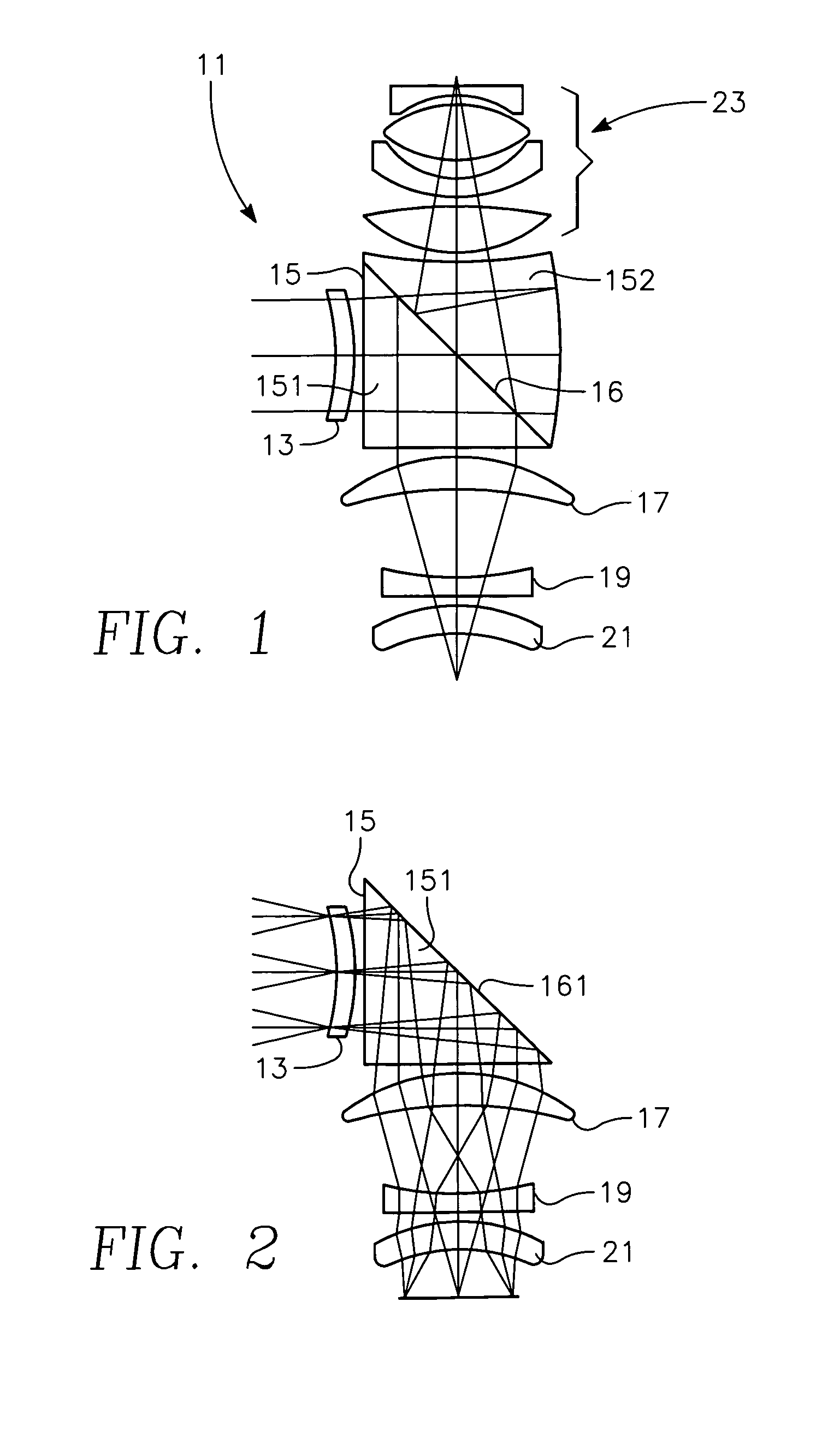
[0016] Referring to the figures, FIG. 1 shows a layout of the optical components of the multi-spectral objective lens 11. The lens combines two different optical pathways with a novel beam-splitter prism. The pathways will be described herein as the “SWIR arm” in reference to the Short-Wave Infrared imager, and the “LWIR arm” in reference to the Long-Wave Infrared imager. Both arms are shown integrated in FIG. 1. Note that both arms share the same primary optical lens 13 and the same prism 15. Both of these elements are made of Zinc Selenide, which is one of very few optical materials that will transmit both SWIR and LWIR. The common optical path passes through the primary lens 13 and the prism 15 to the 45-degree angled face 16 of the beam splitter. This prism surface of the angled face must be optically coated as hereinafter described to reflect the LWIR and transmit the SWIR.

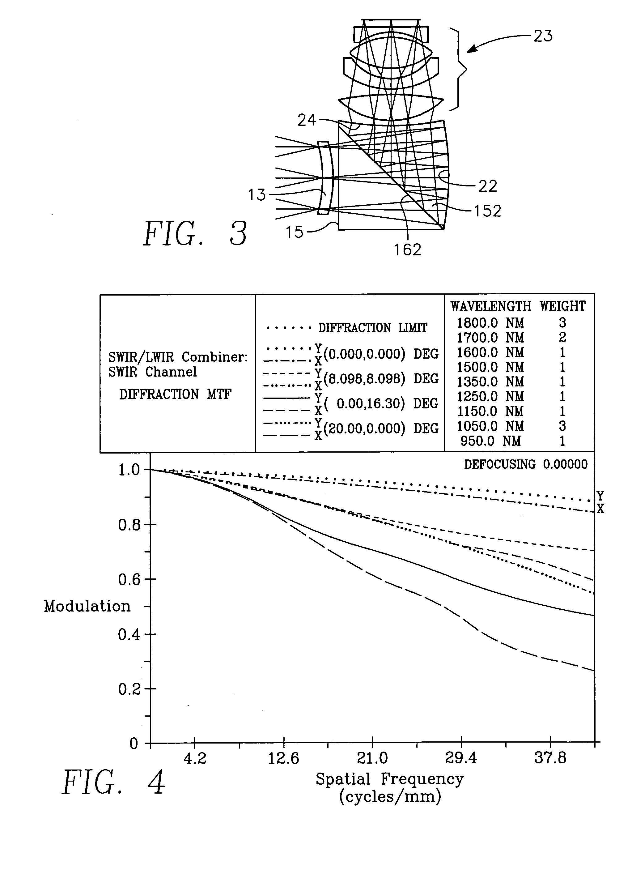
[0017] This optical path description is now continued referring to FIG. 2 and FIG. 3, which respectively ...


PUM


Abstract

A multi-spectral objective lens comprising a primary lens for receiving light reflected from an object, the light including wavelengths in the SWIR and LWIR spectral bands, and optical elements spaced from the receiving means for simultaneously imaging the SWIR light in one focal plane and the LWIR light in another focal plane, thereby allowing real-time image and sensor fusion.

Description

Government Interest [0001] The invention described herein may be manufactured, used, sold, imported, and / or licensed by or for the Government of the United States of America.BACKGROUND OF THE INVENTION [0002] This invention relates in general to optics, and more particularly, to optical sensing apparatus. [0003] Infrared focal plane sensors sense objects by imaging infrared light reflected from the objects. Because different substances interact with light in different ways, and different atmospheric conditions can uniquely hinder the transmission of several wavelengths, it is desirable to image many different wavelengths or regions of the infrared electromagnetic spectrum. [0004] In the following, the terms SWIR and LWIR light will be used. By SWIR it is meant short-wave infrared, or the region of the electromagnetic spectrum between the wavelengths of 1000 nm and 2000 nm. By LWIR is meant long-wave infrared, or the region of the electromagnetic spectrum between the wavelengths of 8...

Claims


Application Information

Patent Timeline
Patent Type & Authority Applications(United States)
IPC IPC(8): G02B13/14
CPCG02B13/146G02B27/1073G02B27/1013
Inventor BRYANT, KYLE R.
Owner ARMY UNITED STATES OF AMERICA AS REPRESENTED BY THE
Why Eureka
Try Eureka