Advanced Magnification Device and Method for Low-Power Sensor Systems

Active Publication Date: 2012-01-26
AVAAK
View PDF6 Cites 15 Cited by
  • Summary
  • Abstract
  • Description
  • Claims
  • Application Information

AI Technical Summary

Benefits of technology

[0010]Briefly, the present invention provides a system and method enabling an advanced optical magnification function for low-power sensors. An image sensor has a set of imager pixels that have a defined field of view. A display device is also provided, which may have, ore or less resolution than the imager. A magnification level is selected, which results in macroblocks (the macroblock is a term used herein to describe the fundamental output of the imager which is not necessarily a pixel, it can be an average of few pixels, Or the output of binning and such) being defined for the sensor. A display data value is generated for each macroblock, and the set of display data values is used to drive a data display. As the magnification level is increased, the number of imager pixels in each macroblock decrease, enabling the display to present increasingly higher resolution images.
[0011]In a more specific example, the advanced magnification function is implemented in a low-power wireless camera, which is substantially powered by battery. Such a device is highly sensitive to resource and power constraints. The low-power wireless camera has an image sensor with a set of imager pixels that have a defined field of view. A display device is also provided, which may have a resolution similar to that of the image. A magnification level is selected, which results in macroblocks being defined for the sensor. A display data value is generated for each macroblock, and the set of display data values are used to drive a data display. As the magnification level is increased, the number of imager pixels in each macroblock decrease, enabling the display to present increasingly higher resolution i

Problems solved by technology

Such a device is highly sensitive

Method used


Image

  • Advanced Magnification Device and Method for Low-Power Sensor Systems
  • Advanced Magnification Device and Method for Low-Power Sensor Systems
  • Advanced Magnification Device and Method for Low-Power Sensor Systems

Examples


Embodiment Construction

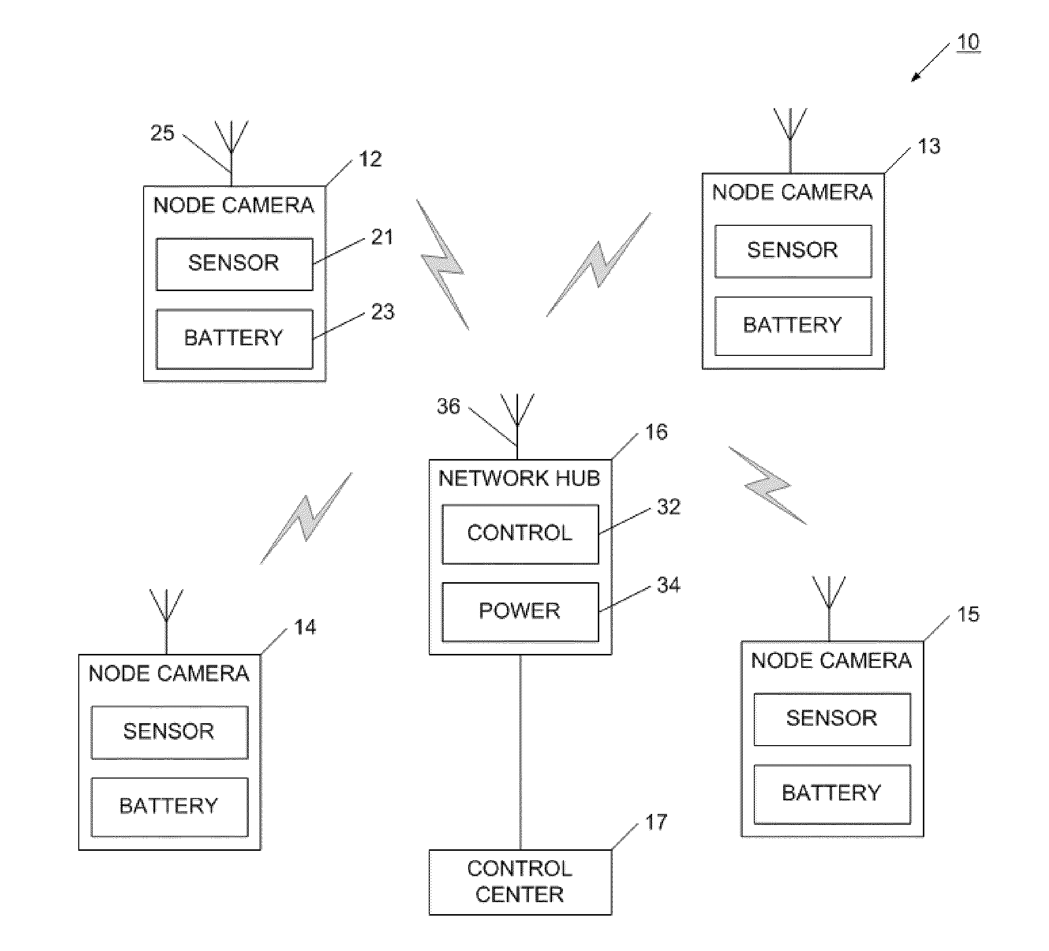
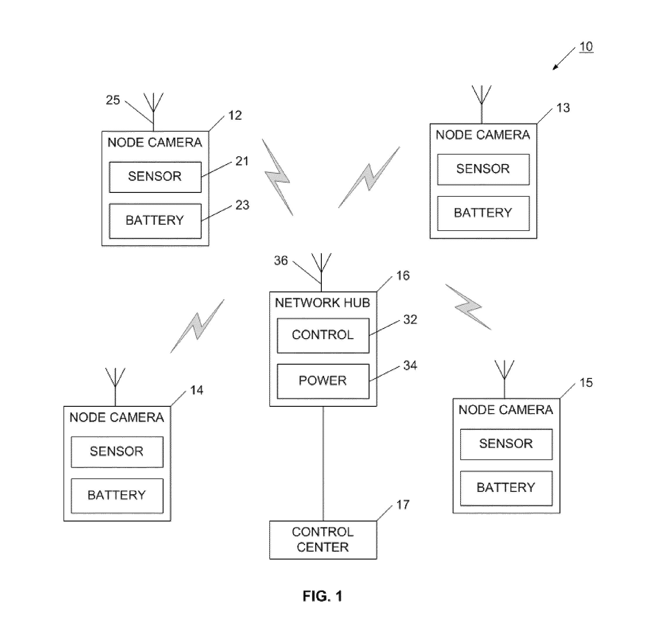
[0027]Referring now to FIG. 1, an advanced magnification system is illustrated in operation on a set of low-power camera sensors. Low-power camera system 10 has a set of node cameras constructed to communicate with network hub 16. More specifically, FIG. 1 shows camera 12, camera 13, camera 14, and camera 15 wirelessly communicating with network hub 16. It will be appreciated that more or fewer cameras may be used, and that node cameras may be provided with different functionality. For example, some node cameras may be constructed to image invisible light, while others may be configured to monitor other wavelengths or to have sensors for detecting other activities. Although low-power camera sensor system 10 is described using visible light and image sensors, it will be appreciated that other types of sensors may be used.

[0028]For example, the sensors may provide acoustic, seismic, spectral, vibration, or other types of information. Each of the node cameras in low-power sensor system...


PUM


Abstract

A system and method is provided for enabling an advanced optical magnification (zooming) function for low-power sensors, such as a remote wireless camera, using electronic methods and enabling that magnification be performed in any part of the imager. An image sensor has a set of imager pixels that have a defined field of view. A display device is also provided, which has a far lower resolution than the imager. A magnification level is selected, which results in macroblocks being defined for the sensor. A display data value is generated for each macroblock, and the set of display data values is used to drive a data display. The area of magnification is flexibly selected on the imager. As the magnification level is increased, the number of imager pixels in each macroblock decrease, enabling the display to present increasingly higher resolution images. Accordingly, an aesthetically pleasing magnification function is provided for a low-power, battery operated mobile environment.

Description

[0001]This application is related to U.S. patent application Ser. No. 11 / 210,411, filed Aug. 24, 2005, and entitled “Network Sensor System and Protocol”; and to U.S. patent application Ser. No. 11 / 210,411, filed Aug. 30, 2007, and entitled “Network Sensor System and Protocol”, both of which are incorporated herein in its entirety.FIELD OF THE INVENTION[0002]The present invention relates to remote imagers and their associated presentation for displaying images with a novel way for zooming at various levels of magnification in arbitrary areas of the image. More particularly, the present invention relates to a set of cameras or network cameras operating their associated image sensors and image processes in a way that conserves resources and power.BACKGROUND[0003]The field of remote sensing is growing rapidly. Remote sensing has been found to be useful in security applications, as well as for monitoring environmental, commercial and industrial processes. It has also proved useful in mod...

Claims


Application Information

Patent Timeline
IPC IPC(8): H04N5/262H04N5/225
CPCH04N5/23296H04N23/69
Inventor GOLDBERG, BAR-GIORAMESSINGER, GIOIAMCGILL, CHRISTOPHER
Owner AVAAK
Why Eureka
Try Eureka