High Spatial Resolution X-ray and Gamma Ray Imaging System Using Crystal Diffraction Lenses

a technology of crystal diffraction and imaging system, applied in tomography, applications, instruments, etc., can solve the problems of inability to provide depth information about the source, large additional cost associated with this method, and inability to identify the source in depth, etc., to achieve high purity, high quality, and high resolution image

Inactive Publication Date: 2005-08-11
UNIVERSITY OF CHICAGO
View PDF3 Cites 13 Cited by
  • Summary
  • Abstract
  • Description
  • Claims
  • Application Information

AI Technical Summary

Benefits of technology

[0017] Still another object of the present invention is to provide a method for producing a high resolution image of a radiation source located in a patient. A feature of the invention is the use of high purity and high quality diffracting crystals 1 mm wide or less. An advantage of the invention is the imaging of millimiter size sources into images of comparable size. Another advantage of the invention is the obviation of unnecessary, invasive surgical procedures to locate a tumor.
[0018] Yet another object of the present invention is to provide a radiation imaging method having a fast imaging time. A feature of the invention is the use of scintillation detectors to locate the approximate position of the radiation source and then the use of a high efficiency crystal diffraction system to produce a high resolution image of the source that can be viewed by a multi-element detector array. An advantage of the invented method is that the amount of radiation necessary to produce a high resolution image is relatively small compared to typical pure scintillation detector methods. Another advantage of the invented method is that one may not have to scan the source in order to obtain a full image thereof.
[0019] Another object of the present invention is to provide a radiation imaging method wherein there is a sharp one to one correspondence between source location and image location. A feature of the invention is the use of narrow apertures between the sources and the detectors. Another feature of the invention is the use of arrays of small size detectors to image the radiation. An advantage of the invented method is a sharp image of the radiating source as recorded by the detectors.
[0020] Another object of the present invention is to provide an economical and manageable imaging device. A feature of the invention is that each of its lenses is made of a plurality of thin, long, and arcuately bent individually mounted crystal units. An advantage of the invention is that a lens can be built rapidly and that a defective crystal in one of the lenses can be replaced quickly and at low cost. Should an individual lens become damaged in a multi-lens system, the lens can be replaced quickly and at low cost. The modular nature of the multi-lens system makes it possible to operate even though some of the crystals in a lens are damaged and even when the whole damaged lens is removed.
[0021] Still another object of the present invention is to allow the imaging system to observe radiation of a selected energy to the exclusion of other energies. A feature of the present invention is that the focal length of the lens depends very sensitively on the energy of the radiation. An advantage of the present invention is that the lens can be so constructed as to focus only radiation of the desired energy.
[0022] In brief the present invention provides a method for high spatial resolution imaging of a source of radiation comprising: a) using high purity and high quality diffracting crystals having a thickness of not more than 1 mm to focus the radiation onto a detector; b) analyzing said focused radiation to collect data as to the type and location of the radiation; and c) producing an image using the data. The invented method can be further enhanced by using a) long diffracting crystals bent in an arcuate shape, b) a multi-element detector array, and c) by positioning narrow apertures in front of the source and in front of the detector.

Problems solved by technology

As such, the technique provides no depth information about the source.
There are considerable additional costs associated with this method and the fact that this method has been introduced in spite of the additional costs underscores the importance of three-dimensional imaging.
Numerous drawbacks exist with scintillation detector tomography.
For instance, the typical coarse resolution of no less than 8 mm often results in smaller structures being overlooked.
This is especially a disadvantage in the detection of breast cancer tumors wherein the tumors often become virulent before growing to a detectable size.
Unfortunately then, positive mammography results often lead to unnecessary surgical operations.
Also, because poor spacial resolution often causes images of actual small tumors to be diffuse, variations in background radiation are often mistaken for actual tumors, leading to unnecessary surgical operations.
Another drawback to using imaging techniques incorporating scintillation detectors is that all of the various radiations emitted by the source are detected by the detectors.
As such, a specific radiation having an energy indicative of a specific, injected isotope cannot be easily scrutinized.
Lastly, because collimators allow for the detection of only the radiation that is emitted in a very narrow direction in space, the patient has to be injected with a relatively large amount of radioactive material.
Such improvements entail considerable expenditures and have the additional drawback that the improvement in resolution has come at the cost of a decrease in counting rate.
Furthermore, the prospects for further improvements in resolution are limited by the fact that such improvements require collimators with ever smaller apertures, and therefore greater mass, together with lower count rates.

Method used


Image

  • High Spatial Resolution X-ray and Gamma Ray Imaging System Using Crystal Diffraction Lenses
  • High Spatial Resolution X-ray and Gamma Ray Imaging System Using Crystal Diffraction Lenses
  • High Spatial Resolution X-ray and Gamma Ray Imaging System Using Crystal Diffraction Lenses

Examples


Embodiment Construction

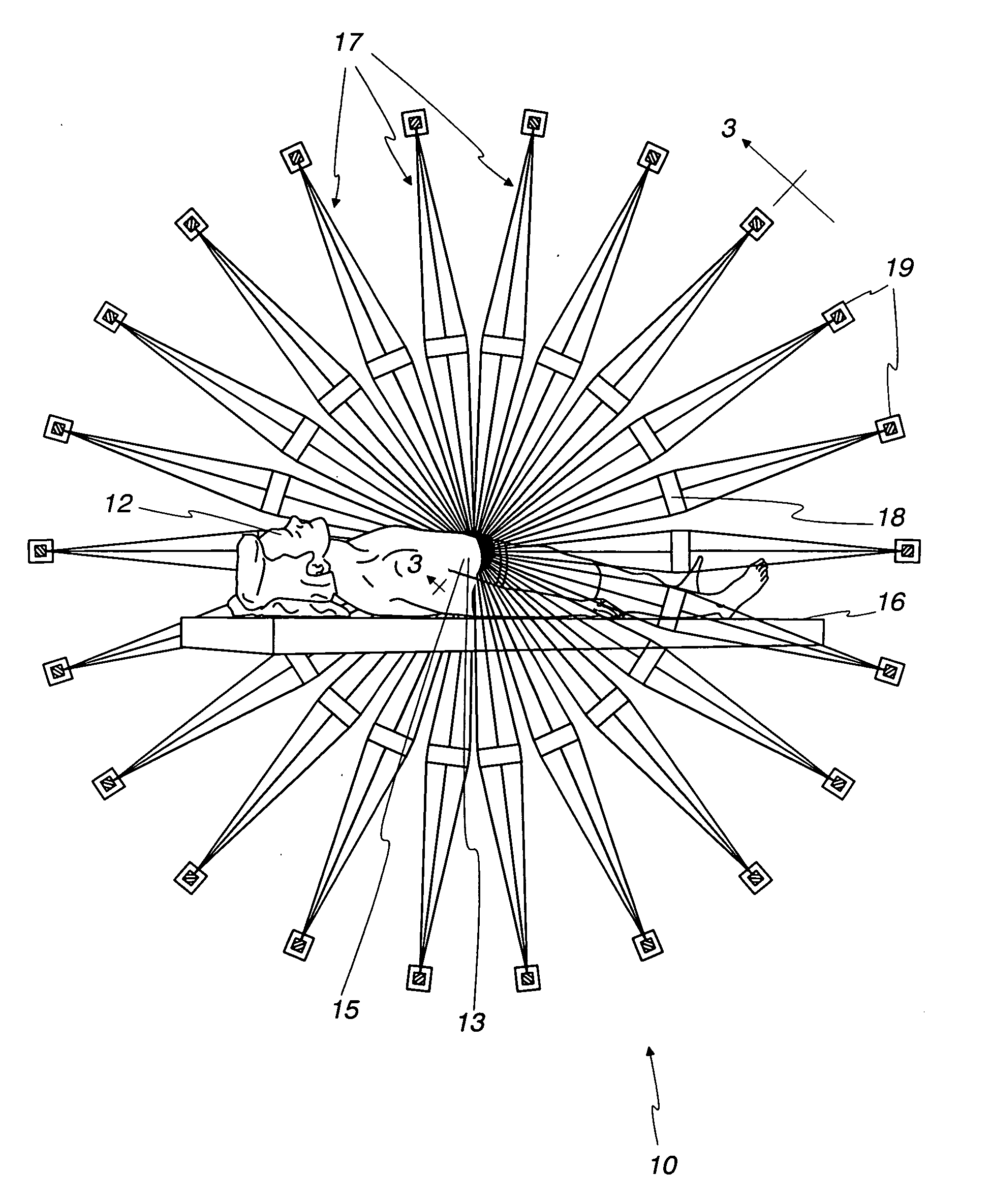
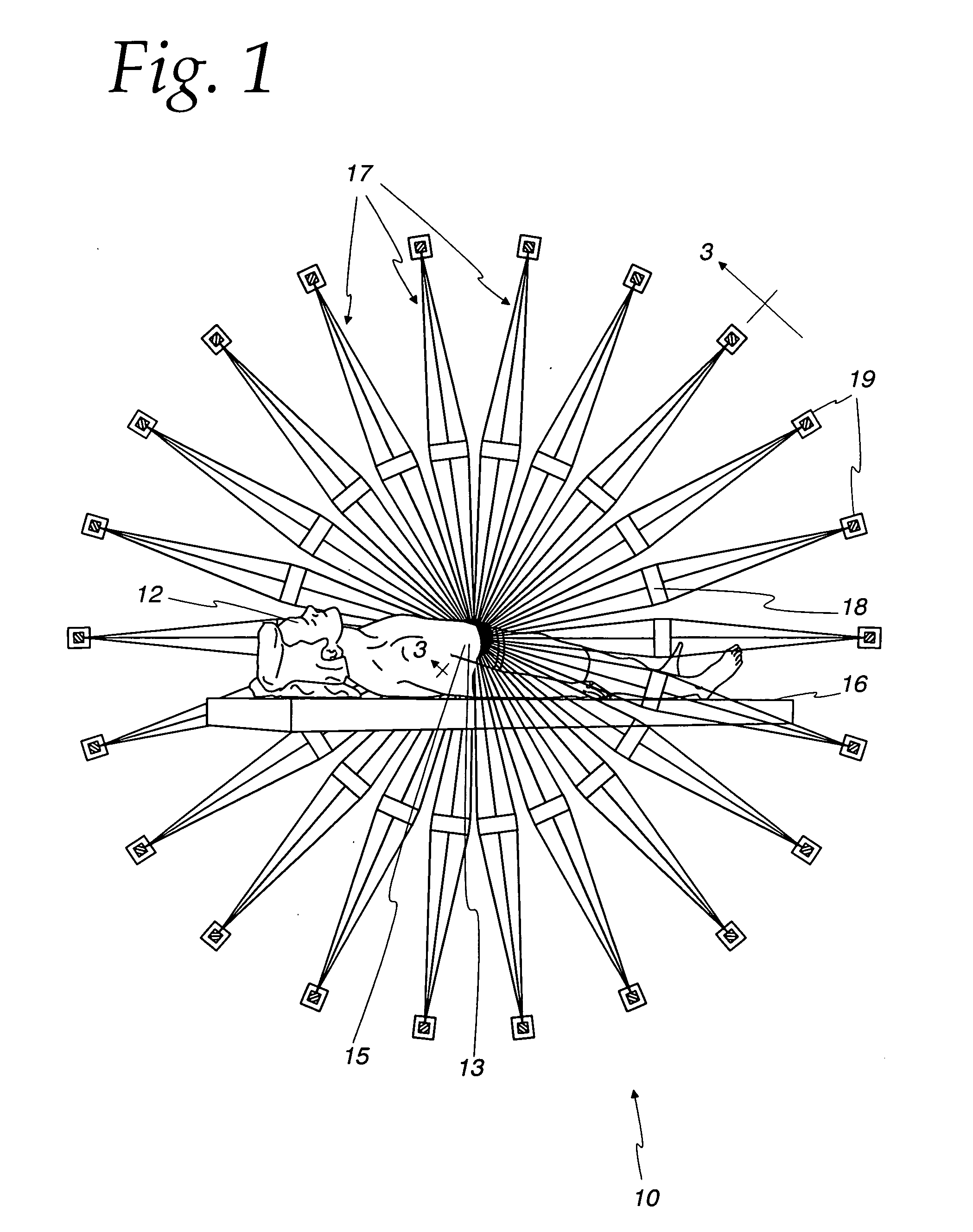
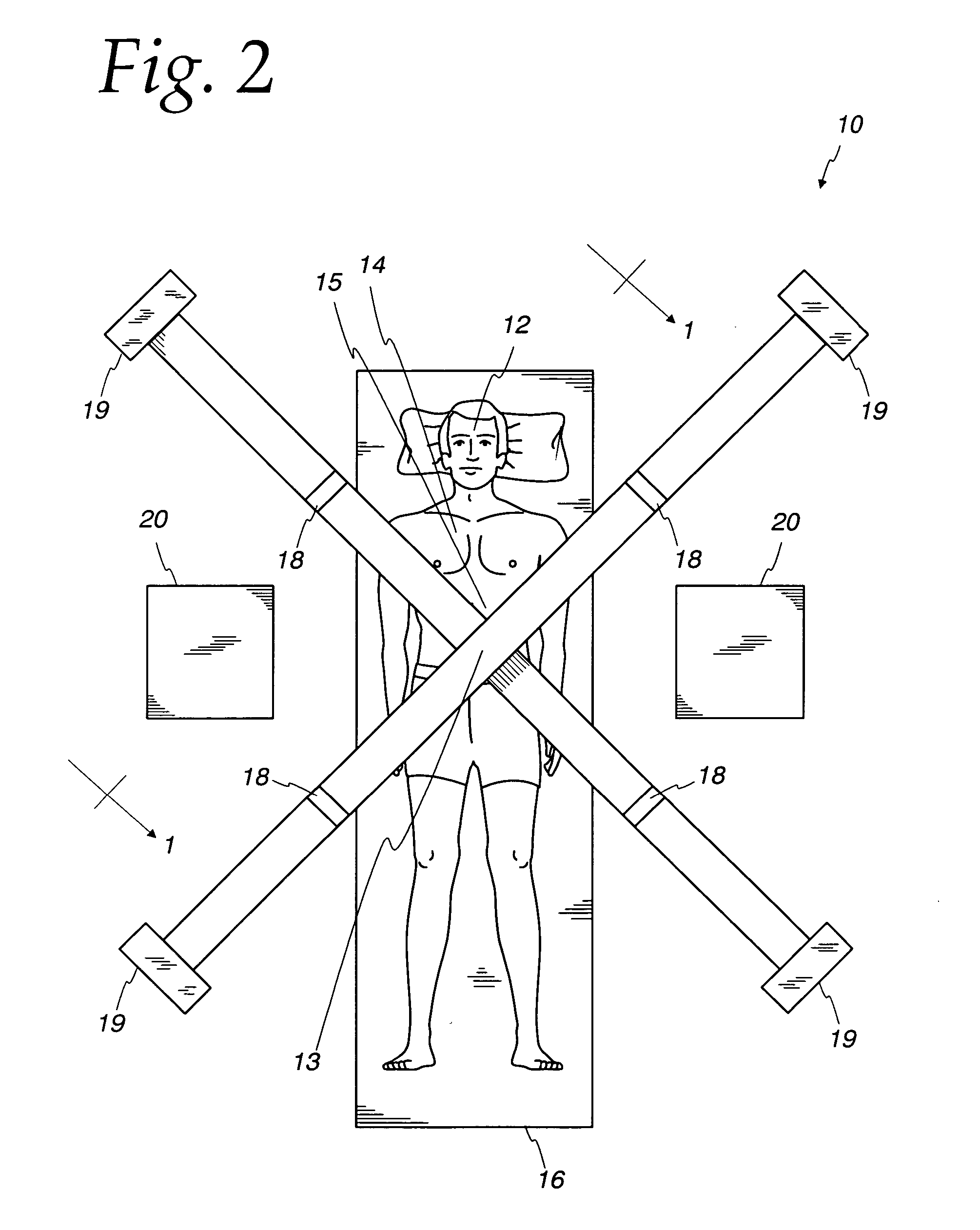
[0047] The present invention provides an improved method for imaging sources of x-ray and gamma-ray radiation. The invented method can yield a detected image 1 mm or less in size (Full Width at Half Maximum (FWHM) for a point source). The method results in a device, designated generally as numeral 10 in FIG. 1, that incorporates a plurality of lens / detector assemblies 17 to first focus and then detect radiation emanating from a radioactive source 15, such as a tumor in a patient 12 that has incorporated some radioactivity as it grows. Each lens / detector assembly 17 comprises a plurality of high efficiency and high resolution crystal diffraction lenses 18 that focus onto detector arrays 19 only the radiation of a desired energy and origin. As disclosed infra, and with reference to FIGS. 6 and 7, each lens 18 comprises a plurality of concentric rings 45, which in turn are comprised of very accurately mounted diffracting crystals. These crystals are oriented so that only radiation havi...


PUM

PropertyMeasurementUnit
widthaaaaaaaaaa
sizeaaaaaaaaaa
thicknessaaaaaaaaaa

Abstract

A method for high spatial resolution imaging of a plurality of sources of x-ray and gamma-ray radiation is provided. High quality diffracting crystals of 1 mm width are used for focussing the radiation and directing the radiation to an array of detectors which is used for analyzing their addition to collect data as to the location of the source of radiation. A computer is used for converting the data to an image. The invention also provides for the use of a multi-component high resolution detector array and for narrow source and detector apertures.

Description

CONTRACTUAL ORIGIN OF INVENTION [0001] The United States Government has rights to this invention pursuant to Contract No. W-31-109-ENG-38 between the U.S. Department of Energy and the University of Chicago, representing Argonne National Laboratory.BACKGROUND OF THE INVENTION [0002] 1. Field of the Invention [0003] This invention relates to a method for improving the imaging a source of radiation and to a device for imaging a source of radiation, and more specifically, this invention relates to a method and device for producing a high spatial resolution three-dimensional image of a source of x-ray and gamma-ray radiation for medical and other application by using a plurality of diffracting crystals which focus x-ray and gamma-ray radiation onto a plurality of detection devices. [0004] 2. Background of the Invention [0005] Cancer tumor cells have high rates of metabolism and multiply rapidly. Substances injected into the body tend to migrate to locations of such high growth and become...

Claims


Application Information

Patent Timeline
Patent Type & Authority Applications(United States)
IPC IPC(8): A61B6/00G01N23/00G01N23/207G21K1/06G21K1/12H05G1/60
CPCA61B6/037G01N23/207G21K2201/064G21K2201/062G21K1/06
Inventor SMITHER, ROBERT K.
Owner UNIVERSITY OF CHICAGO
Why Eureka
Try Eureka