Wrenchless blade clamp assembly

a clamp assembly and wrench technology, applied in the direction of screw, threaded fastener, load modification fastener, etc., can solve the problems of cumbersome use of wrenches, inconvenient use, time-consuming appropriate wrenches, etc., to avoid the need for tools, improve the effect of manual tightening and/or loosening and improving the blade clamp assembly

Inactive Publication Date: 2005-01-18
CREDO TECH CORP
View PDF17 Cites 27 Cited by
  • Summary
  • Abstract
  • Description
  • Claims
  • Application Information

AI Technical Summary

Benefits of technology

An advantage of the present invention is to provide an improved blade clamp assembly. Another advantage of the present invention is to provide a blade clamp assembly which can be manually tightened and / or loosened, avoiding a need for a tool.
A further advantage of the present invention is to provide an improved blade clamp assembly which maintains an optimal clamping force against a saw blade and which prevents overtightening of the bolt during installation of a blade.
Still another advantage of the present invention is to provide a blade clamp assembly which prevents the click bolt from becoming overtightened, thereby permitting the bolt to be removed manually later.
A still further advantage of the present invention is to provide a blade clamp assembly which minimizes the time and inconvenience of installing, removing and / or interchanging a blade of a circular saw.
The wrenchless blade clamp assembly includes operative components which, in an embodiment, are advantageously located on an outer side of a saw blade or tool disc, yet which have a low profile to avoid interference with a workpiece.

Problems solved by technology

Inconveniences are incurred by the use of a conventional bolt to mount a circular saw blade.
For example, the task of obtaining an appropriate wrench can be time consuming, and using the wrench can be cumbersome.

Method used


Image

  • Wrenchless blade clamp assembly
  • Wrenchless blade clamp assembly
  • Wrenchless blade clamp assembly

Examples


Embodiment Construction

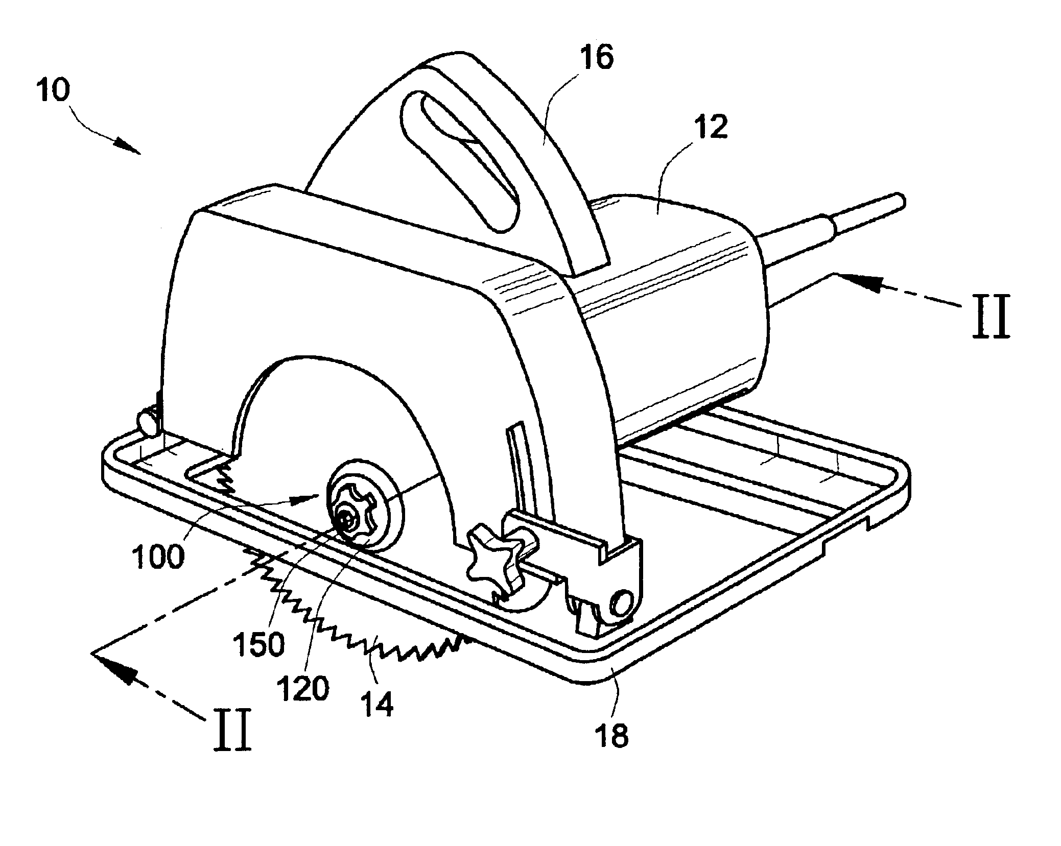
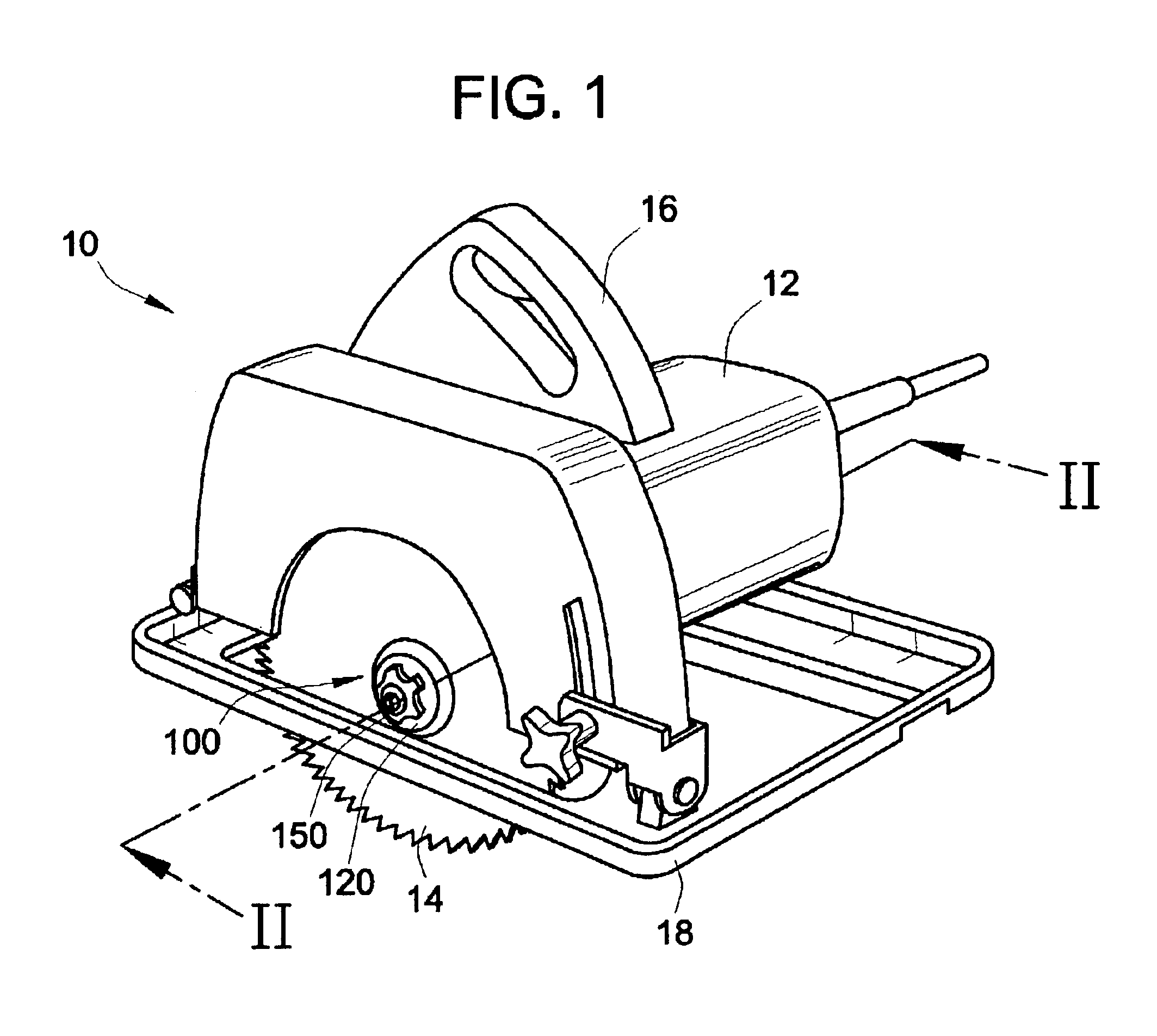
Now referring to the drawings, wherein like numerals designate like components, FIG. 1 illustrates a circular saw 10. The saw 10 includes a housing 12 and a circular blade 14 rotationally driven, through a gear reduction, by a motor within the housing. In the illustrated embodiment, the housing 12 is shaped to include a handle portion 16 to be gripped by a user, with a switch mounted to the handle portion for actuating the motor. The saw 10 also includes a foot plate 18 to support the saw 10 against a work piece during use.

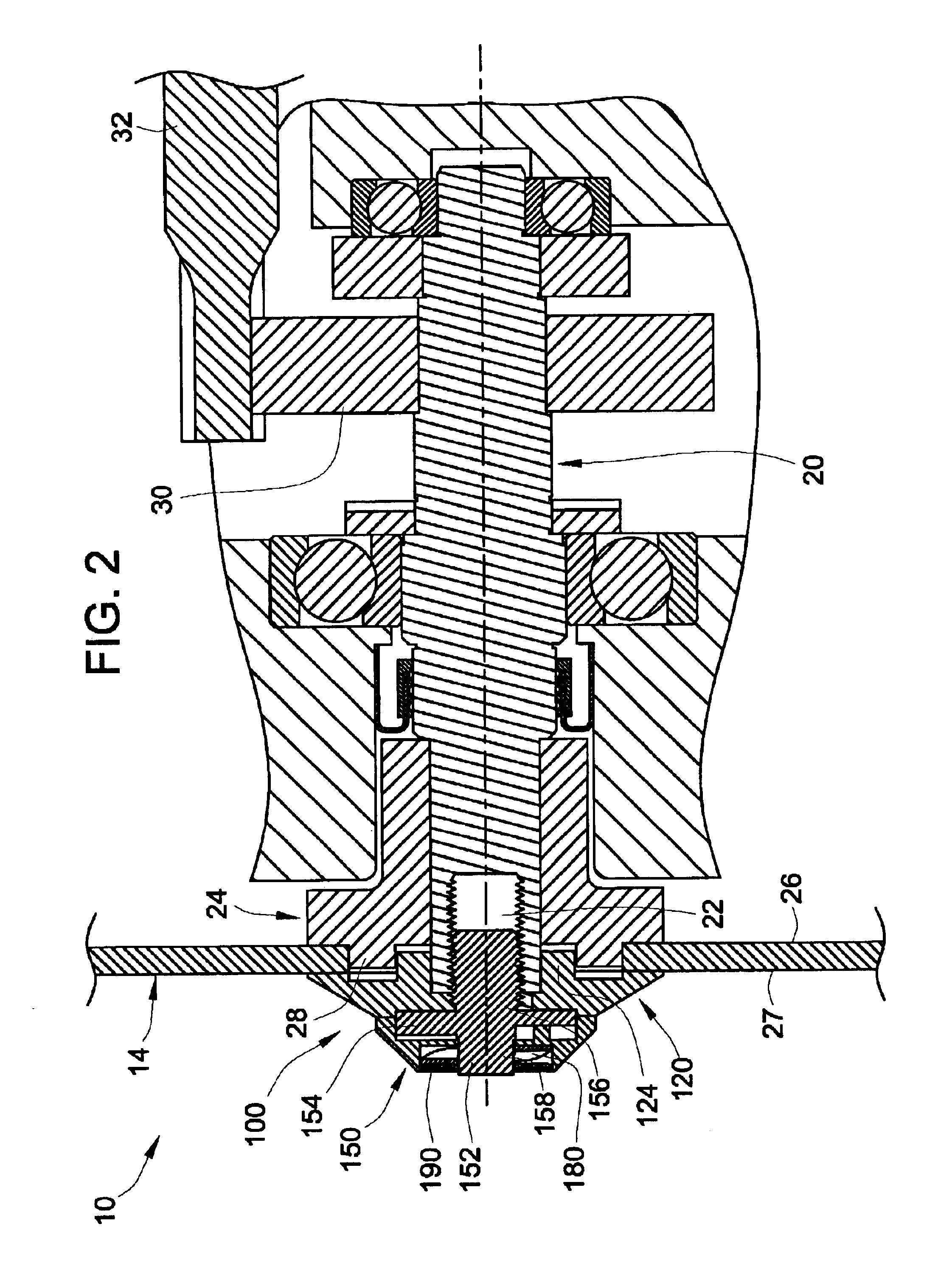
Referring to FIG. 2, the saw 10 includes a shaft 20 that is rotationally driven by the motor (not shown) through a gear 30 and spindle 32. The shaft 20 includes an axially oriented bore 22 that opens at a mounting end of the shaft. The bore 22 has internal threads. The saw 10 further includes an inner flange 24 that is mounted to the shaft 20 at an inner side of the blade 14. In order to rotationally fix the inner flange 24 to the shaft 20, the shaft is form fit t...


PUM

PropertyMeasurementUnit
depthaaaaaaaaaa
resistanceaaaaaaaaaa
torqueaaaaaaaaaa

Abstract

A wrenchless clamp assembly is provided to secure a tool disc, such as a circular saw blade, to a shaft of a power tool. The blade clamp assembly includes an outer flange positionable against an outer side of the blade and a manually tightenable click bolt that includes a movable click member operable to selectively engage the outer flange for rotationally locking or unlocking the bolt. In an embodiment, the click member moves alternatingly between axially engaged and disengaged positions according to sequential rotational increments of the click member relative to the bolt body. Accordingly, the click bolt can be installed by hand and rotationally locked without a need for high torque, and the click bolt can be easily removed by hand when the click member is moved to the disengaged position, axially free from the outer flange. In an embodiment, the click bolt permits limited torque applied during installation.

Description

FIELD OF THE INVENTIONThe present invention generally relates to rotary power tools and more particularly to a wrenchless blade clamp assembly for securing a blade of a circular saw.BACKGROUND OF THE INVENTIONA circular saw generally includes a circular blade having a centrally located hole for mounting the blade to a rotatable shaft. The blade is conventionally mounted to end of the rotatable shaft in compression between an inner flange and outer flange or washer, held by a conventional bolt threaded into a threaded bore in the shaft. In order to apply sufficient torque to the bolt for installing or removing the blade, a wrench must be used.Inconveniences are incurred by the use of a conventional bolt to mount a circular saw blade. For example, the task of obtaining an appropriate wrench can be time consuming, and using the wrench can be cumbersome. It is, therefore, desirable to have a quicker and simpler way to manually secure a blade to the rotating shaft of a circular saw witho...

Claims


Application Information

Patent Timeline
Patent Type & Authority Patents(United States)
IPC IPC(8): B27B5/32B27B5/00
CPCB27B5/32Y10S411/919Y10T83/7747
Inventor CHILDS, DANIEL K.HOUBEN, JAN PETERHOLZER, MICHAELBUJALSKI, LEON
Owner CREDO TECH CORP
Why Eureka
Try Eureka