Air filter

a filter and air technology, applied in the field of air filters, can solve the problem that carbon particles cannot be effectively captured over the entire thickness of the second filter layer, and achieve the effect of reducing costs

Inactive Publication Date: 2005-01-18
TOYO ROKI MFG CO LTD +1
View PDF16 Cites 154 Cited by
  • Summary
  • Abstract
  • Description
  • Claims
  • Application Information

AI Technical Summary

Benefits of technology

An object of the present invention, which was made in view of the above-described circumstances, is therefore to provide an air filter, which permits to provide a large amount of captured dust per volume of the filter, capture effectively carbon particles and reduce costs.
According to the present invention, it is possible to prevent oil from adhering to the downstream end of the second filter, permitting a more effective capture of the carbon particles utilizing the second filter layer.

Problems solved by technology

On the contrary, in case where the second filter layer is provided only in the upstream portion with a lipophobic layer, the oil in the first filter layer may penetrate through the lipophobic layer, thus causing a problem that the carbon particles cannot be captured effectively over the entire thickness of the second filter layer.

Method used


Image

  • Air filter
  • Air filter
  • Air filter

Examples


first embodiment

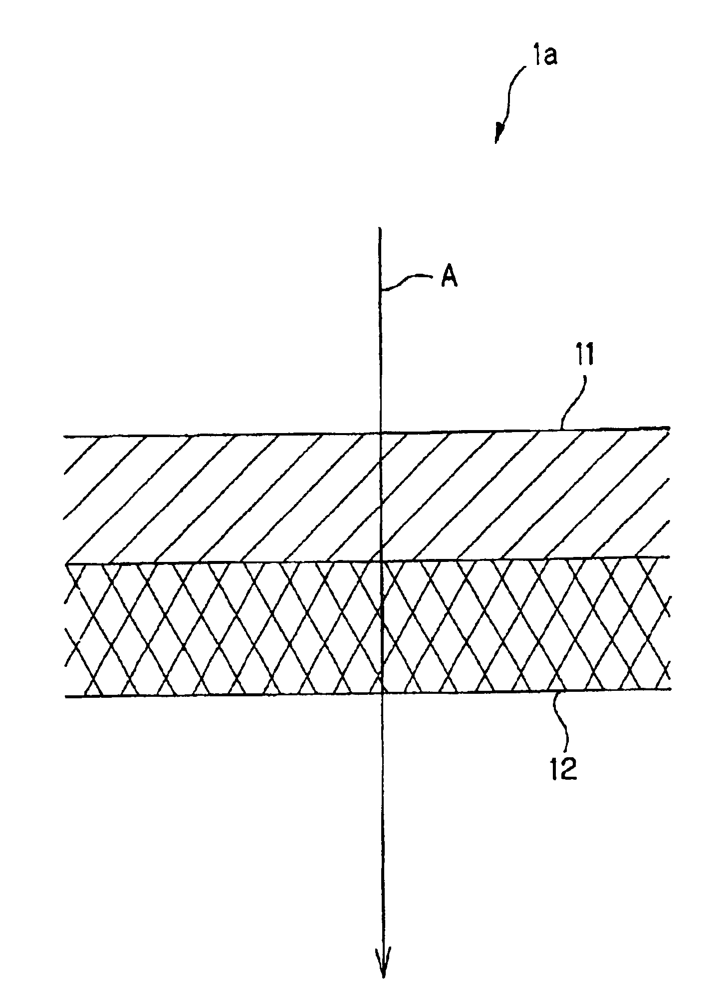
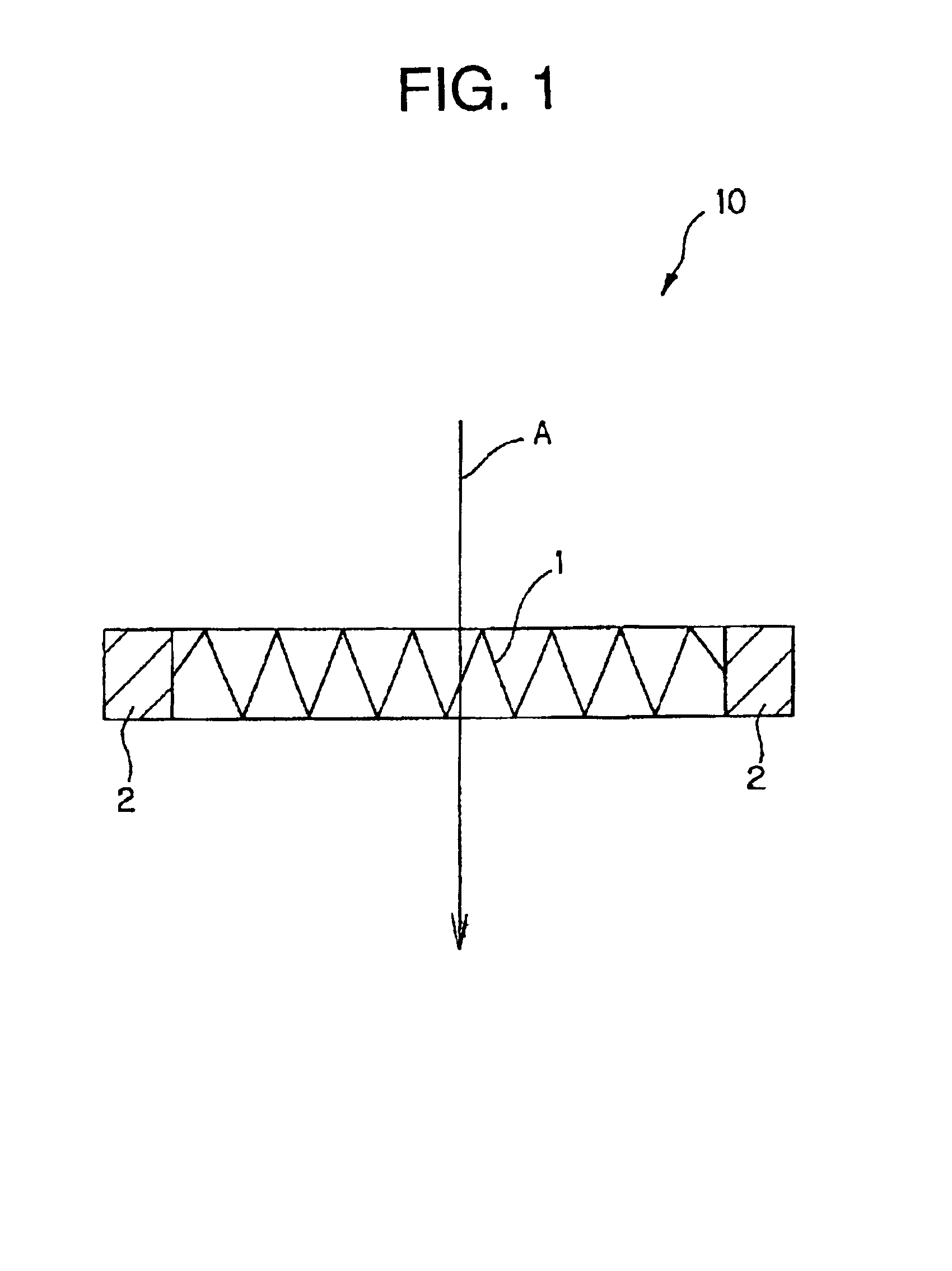
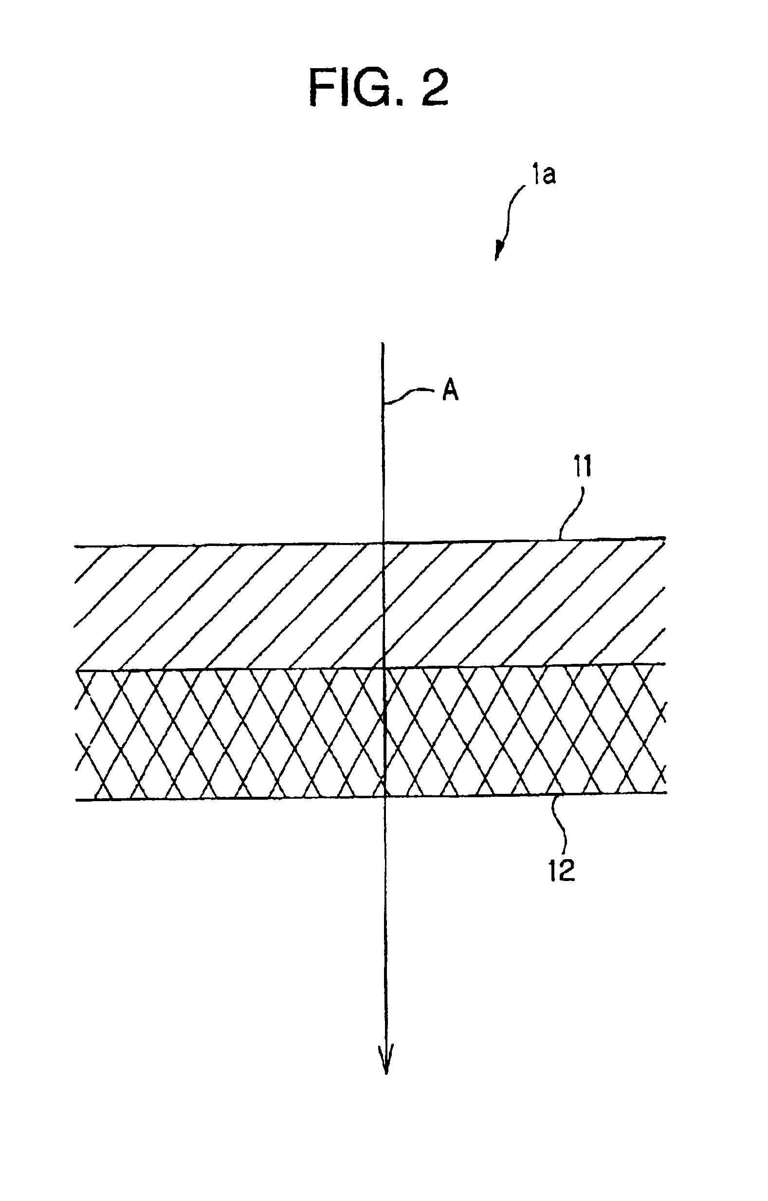
The filter element 1a of the first embodiment as shown in FIG. 2 is provide with the first filter layer 11 having filter element impregnated with oil such as viscose oil and the second filter layer 12, which is composed of a lipophobic layer having an oil-repellent property. Both the first filter layer 11 and the second filter layer 12 are formed of filter paper. The filter material of the first filter layer 11 has a higher density than the filter material of the second filter layer 12. The second filter layer 12 is formed as the lipophobic layer over the entire thickness, i.e., from the upstream-side end face 12a to the downstream-side end face 12b so as to prevent or inhibit oil impregnated in the first filter layer 11 from entering the second filter layer 12 under the function of the oil-repellent property of the lipophobic layer. The downstream-side end face 12b of the second filter layer 12 is exposed to come into contact with air. The upper surface of the first filter layer 11...

second embodiment

In the second embodiment as shown in FIG. 3(A), the filter element 1b is obtained by combining the first filter layer 11 having the filter material impregnated with oil and the second filter layer 12 composed of the lipophobic layer by an adhesive layer 13. The first filter layer 11 and the second filter layer 12 are joined together so as to permit air to pass through the contacting surfaces of these layers. After completion of the manufacturing steps, the adhesive agent 13 permeates into the first filter layer 11 and the second filter layer 12 so as not to form any gap between the first filter layer 11 and the second filter layer 12 as shown in FIG. 3(B). Also in the embodiment the upper surface of the first filter layer 11 oozes with the oil impregnated in the first filter layer 11 to provide a condition in which dust can easily be captured. Imparting the oil-repellent property to the second filter layer 12 makes it possible to provide a filter layer for capturing carbon particles...

third embodiment

The filter element 1c of the third embodiment as shown in FIG. 4 is provided with the first filter layer 11 having the filter material impregnated with oil, the first intermediate layer 15, the second intermediate layer 16 and a clean layer 17, which are disposed in this order from the upstream side to the down stream side. In the embodiment, the second filter layer composed of the lipophobic layer having the oil-repellent property serves as any one of the first intermediate layer 15, the second intermediate layer 16 and the clean layer 17. With respect to the other layer, material, a pore size, thickness and the other conditions may be determined taking into consideration object of use of the filter. The material for the other layer may be formed for example of filter paper or non-woven fabric. In case where the filter paper is used, a water-repellent treatment applied to it makes it possible to prevent water from being sucked into the inside of an engine, even when a suction port ...


PUM

PropertyMeasurementUnit
pore sizeaaaaaaaaaa
pore sizeaaaaaaaaaa
sieve diameteraaaaaaaaaa

Abstract

There is provided an air filter, which has a long lifetime and permits to capture effectively carbon particles and reduce costs. The air filter has the first filter layer 11 impregnated with oil and the second filter layer 12, which is provided on the downstream side of the first filter layer 11 and serves as a lipophobic layer having an oil-repellent property. The filter material of the first filter layer 11 has a higher density than the filter material of the second filter material 12.

Description

TECHNICAL FIELDThe present invention relates to an air filter, and especially to an air filter, which permits to capture efficiently carbon particles.BACKGROUND OF THE INVENTIONAs an air filter for a vehicle, there has been known a wet-type filter having filter paper impregnated with oil. Viscose oil is generally used as impregnation oil. Accordingly, it is called the “viscose type” air filter. The viscose type air filter has an advantage of extended lifetime in comparison with the dry-type filter, which is not impregnated with oil. In the viscose type air filter, oil on the surface of the filter captures dust and then the oil penetrates into the captured dust so as to provide a function of capturing the other dust on the surface of the captured dust. Such a chain capture of dust permits to increase an amount of captured dust per volume of the filter.Japanese Utility Model Publication No. S63-27767 describes the improved viscose type air filter. The air filter described in Japanese ...

Claims


Application Information

Patent Timeline
Patent Type & Authority Patents(United States)
IPC IPC(8): B01D39/18B01D39/00F02M35/024B01D39/14B01D46/12B01D46/52
CPCB01D39/18B01D46/0035B01D2275/10
Inventor SUZUKI, ATSUSHIOBA, TOSHINORIMATSUSHITA, NORIHIKOSUZUKI, KATSUMIJO, TAKEO
Owner TOYO ROKI MFG CO LTD
Why Eureka
Try Eureka