
Filtering candles comprising a sintered filtering tube

Inactive Publication Date: 2005-01-18
GKN SINTER METALS GMBH & CO KG
View PDF16 Cites 5 Cited by
  • Summary
  • Abstract
  • Description
  • Claims
  • Application Information

AI Technical Summary

Benefits of technology

This problem is solved according to the invention by means of a filtering candle, comprising a sintered filtering tube and a collar, which is connected to the filtering tube and com-prises an annular collar wall, which is oriented towards the filtering tube and starts from a neck and comprises at least one recess arranged perpendicular and angular in relation to a plane arranged perpendicular to a filtering tube axis. It is no longer possible, due to the specific arrangement of the recess in the filtering candle according to the invention, to mechanically detach the collar from the sintered filtering tube. In addition, the surface of the collar is increased due to the recess, whereby a higher number of points of contact is made available to sinterable material, regardless of whether it is in powder form or fibrous. Thus, the bonding strength between collar and sintered filtering tube is finally increased.
The sinterable powder can consist of powdery and / or spattered particles. Spattered sinterable powders make it in particular possible to obtain filtering tubes and / or collars of at the same time low density and high strength.

Problems solved by technology

If a sintered collar is used, problems arise with respect to the strength of the fil-tering candle, in particular with respect to applications subjecting the filtering candle to heavy mechanical stress.
If filtering candles are used comprising a massive collar, fissures will occur, in particular in the connecting area of massive collar and sintered filtering tube when subjected to heavy mechanical or thermal stress, due to the different na-ture of the collar material and the filtering tube material as well as due to their different physical nature, which in the end cause total damage to the filtering candle, thus heavily reducing the shelf life of such filtering candles.
In particular, today it is still not possible to produce a secure and stable connection between a collar and a sintered filtering tube, if the filtering tube is made from sinterable powder material, which comprises mean diameter exceeding 200 μm, or if the filtering tube is made from sinterable fi-brous material.

Method used


Image

  • Filtering candles comprising a sintered filtering tube
  • Filtering candles comprising a sintered filtering tube
  • Filtering candles comprising a sintered filtering tube

Examples


Embodiment Construction

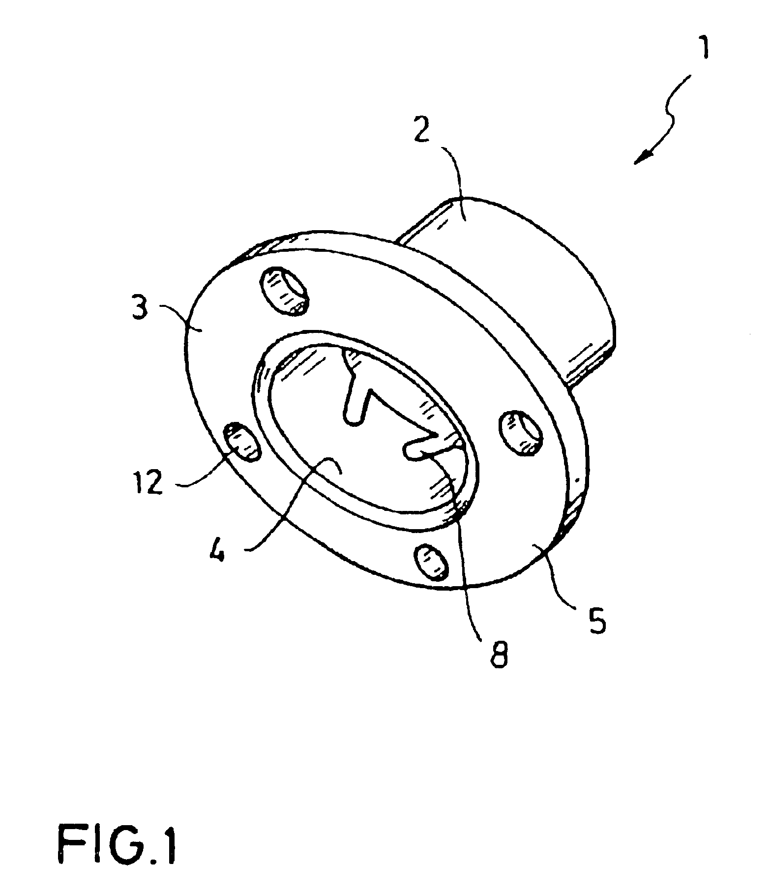
FIG. 1 shows a filtering candle according to the invention, the whole of which is referred to as 1, which consists of a sintered filtering tube 2 and a massive collar 3, made from gray cast iron. The collar 3 comprises a neck 5 with bore-holes 12 to fix the filtering candle 1 to equipment or the like. Furthermore, the collar 3 comprises a collar wall 4 with a recess 8. These recesses 8 are arranged opposite to one another and arranged starting from the end of the collar wall 4 opposite the neck 5 of the collar 3. They are formed as elongated boreholes.

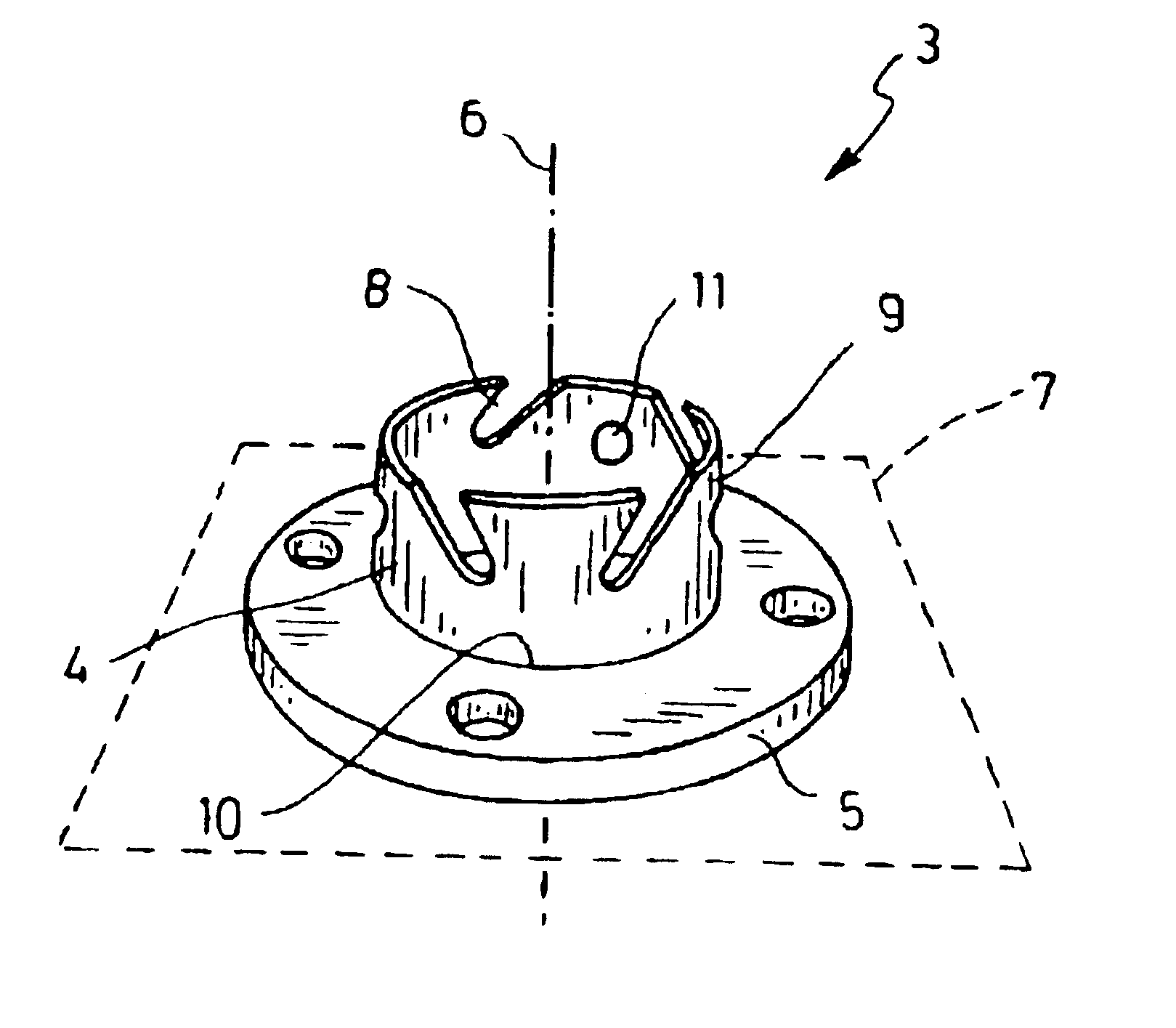
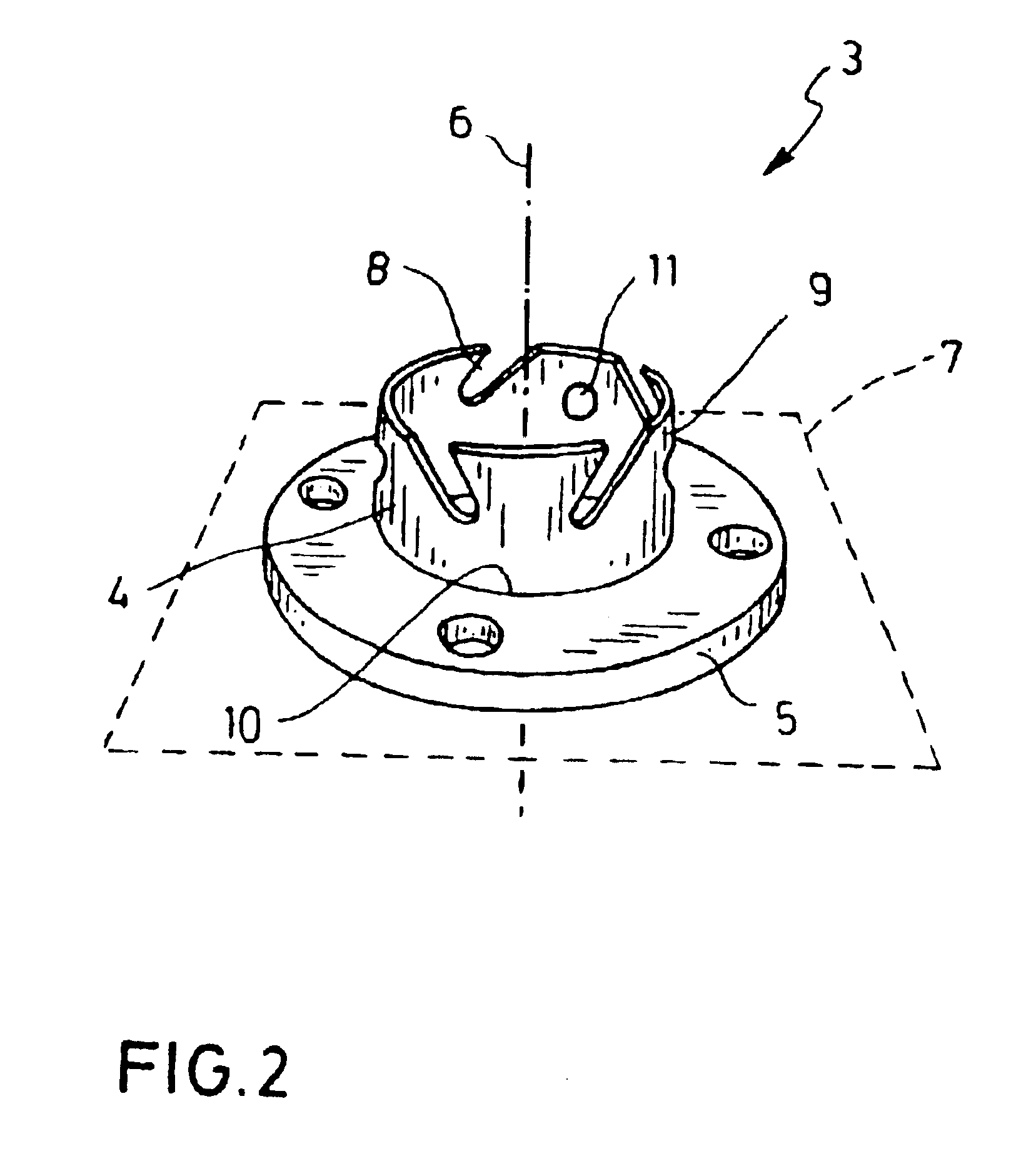
FIG. 2 shows an embodiment of the collar according to the in-vention, as it is also used in the filtering candle 1 accord-ing to FIG. 1. The collar, the whole of which is referred to as 3, comprises several recesses 8, which are arranged in op-posite direction to one another, and between these recesses 8 finger-shaped areas in the collar wall 4. The collar wall 4 further comprises at its outer side grooves 10 running around the circumf...


PUM

PropertyMeasurementUnit
Diameteraaaaaaaaaa
Lengthaaaaaaaaaa
Particle diameteraaaaaaaaaa

Abstract

The aim of the invention is to provide filtering candles (1) comprising a sintered filtering tube (2) and a collar (3) which is connected thereto, and having an increased shelf life and improved resistance values. To this end, the collar (3) comprises an annular collar wall (4) which oriented towards the filtering tube (2) from the neck. Said wall comprises at least one recess (8) which is arranged in a perpendicular manner and at an angle in relation to a plane which is perpendicular to the axis of the filtering tube.

Description

FIELD OF THE INVENTIONThis invention relates to a filtering candle, comprising a sintered filtering tube and a collar connected thereto, as well as to a method to manufacture it and its utilization.BACKGROUND OF THE INVENTIONIn order to fix sintered filtering tubes to / on something or install them, it is known in the art to provide the sintered filtering tube with a sintered or massive collar, i.e. made from cast iron or the like, which comprises fixing means to fix the filtering candle consisting of the sintered filtering tube and the collar to / on something. If a sintered collar is used, problems arise with respect to the strength of the fil-tering candle, in particular with respect to applications subjecting the filtering candle to heavy mechanical stress.If filtering candles are used comprising a massive collar, fissures will occur, in particular in the connecting area of massive collar and sintered filtering tube when subjected to heavy mechanical or thermal stress, due to the di...

Claims


Application Information

Patent Timeline
IPC IPC(8): B01D46/24B01D29/11B22F7/00B01D29/33B01D39/20B01J35/04B22F3/11B22F5/10B22F7/08
CPCB01D29/111B01D46/2407B22F7/004B01D46/0004B22F3/002B22F7/08B22F3/04B22F3/10Y10S264/48B01D2201/043B01D2201/40B01D2273/20B22F2998/00B22F2998/10Y10S55/05
Inventor STEIGERT, SIMON
Owner GKN SINTER METALS GMBH & CO KG
Learn More