Overmodulation systems and methods for induction motor control

a technology of induction motor and overmodulation system, which is applied in the direction of motor/generator/converter stopper, dynamo-electric gear control, motor/generator/converter stopper, etc., can solve the problem of reducing the voltage available to drive current into the motor, and affecting the operation of the motor. problem, to achieve the effect of improving the robustness of the overmodulation strategy and reducing the occurrence of nuisance over

Inactive Publication Date: 2005-01-18
VITESCO TECH USA LLC
View PDF9 Cites 18 Cited by
  • Summary
  • Abstract
  • Description
  • Claims
  • Application Information

AI Technical Summary

Benefits of technology

[0009]Taught herein are systems and methods which improve the robustness of the overmodulation strategy for controlling an induction motor during high-speed operat

Problems solved by technology

This reduces the voltage available to drive current into the motor, and thus limits the ability of the motor to produce torque.
One limitation of overmod

Method used


Image

  • Overmodulation systems and methods for induction motor control
  • Overmodulation systems and methods for induction motor control
  • Overmodulation systems and methods for induction motor control

Examples


Embodiment Construction

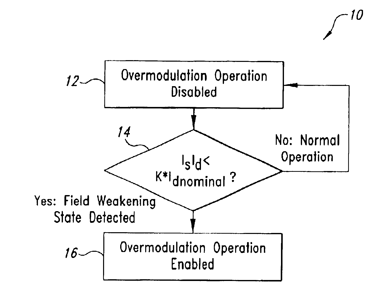
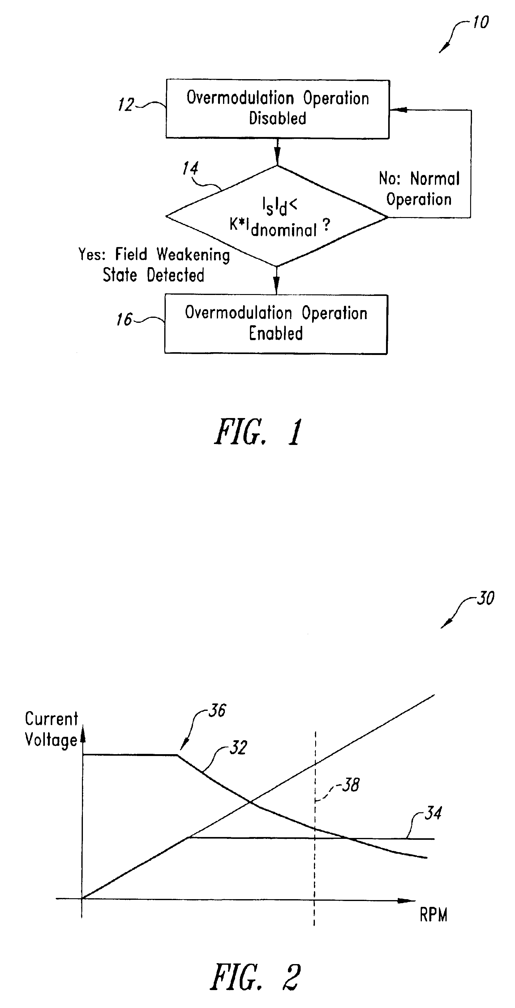
er field weakening has taken effect, highlighting a “corner point” where current and voltage are at their respective limits.

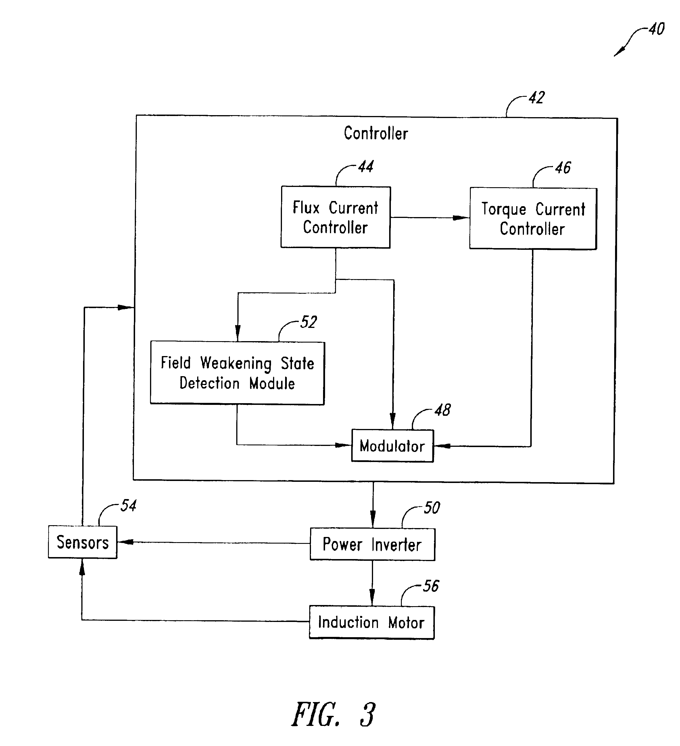
[0014]FIG. 3 is a functional block diagram of one embodiment of a system for carrying out the overmodulation strategy of the present invention.

DETAILED DESCRIPTION OF THE INVENTION

[0015]In the following description, certain specific details are set forth in order to provide a through understanding of various embodiments of the invention. However, one skilled in the art will understand that the invention may be practiced without these details. In other instances, well-known structures associated with electrical circuits and circuit elements have not been shown or described in detail to avoid unnecessarily obscuring descriptions of the embodiments of the invention.

[0016]Unless the context requires otherwise, throughout the specification and claims which follow, the word “comprise” and variations thereof, such as, “comprises” and “comprising” are to be construed i...


PUM


Abstract

Systems and methods for controlling an induction motor including detecting a field weakening operation state of the motor, wherein the field weakening operation state is detected when a flux current, Id, in the motor is reduced to a predetermined fraction of its normal, non-voltage limited value. The systems and methods also including an overmodulation operation state of the motor before said field weakening operation state is detected and enabling the overmodulation operation state of the motor after said field weakening operation state is detected.

Description

BACKGROUND OF INVENTION[0002]1. Field of the Invention[0003]The present invention relates generally to systems and methods for directing and controlling the operation of an induction motor.[0004]2. Background of Invention[0005]The “fuel” powering an induction motor, such as a field-oriented induction motor, is current. This current may be divided into two components, torque current and flux current. Torque current may be viewed as that component of the current which generates motive force, or torque. Flux current may be viewed as that component of the current which generates magnetic flux in the rotor of the motor. Shaft torque and rotor flux are related, with shaft torque proportional to the product of rotor flux and torque current. At high speeds, shaft torque may be calculated using back-EMF voltage.[0006]Typically, in an induction motor, as the speed increases the back-EMF voltage increases as well. This reduces the voltage available to drive current into the motor, and thus lim...

Claims


Application Information

Patent Timeline
IPC IPC(8): H02P23/00
CPCH02P23/0036H02P23/0004
Inventor CHEN, LIHAMPO, RICHARD J.NALLAPA, VENKATAPATHI R.
Owner VITESCO TECH USA LLC
Why Eureka
Try Eureka