Polar loop transmitter

a transmitter and loop technology, applied in the field of polar loop transmitters, can solve the problems of increasing distortion at low instantaneous signal levels, adding unwanted phase modulation to output signals,

Inactive Publication Date: 2005-01-18
INTEL CORP
View PDF7 Cites 38 Cited by
  • Summary
  • Abstract
  • Description
  • Claims
  • Application Information

AI Technical Summary

Benefits of technology

The present technology offers many advantages for polar loop transmitter circuits. More particularly, aspects of the exemplary polar loop transmitter circuit arrangements provided herein provide for careful control of selected signal amplitudes to compensate for any phase variations introduced in such circuit arrangements. When utilizing logarithmic amplifiers in accordance with the present subject matter, additional advantages may be present since the phase of the logarithmic amplifier output signal does not vary with the amplitude of the input signal.
Yet another advantage of aspects of the present technology, especially the amplifiers utilized in the subject polar loop transmitter embodiments, is versatility in design and operation of the amplifier and detector components. Exemplary amplifier designs are disclosed with an ability to afford a variety of different transfer functions and signal modification for signals therein.

Problems solved by technology

The polar loop transmitter 100 suffers certain disadvantages when the variation in input signal amplitude is large, namely that any phase modulation to amplitude modulation conversion caused by the limiting amplifiers 106 and 108 add unwanted phase modulation to the output signal as the amplitude of the input signal varies.
In addition, with large RF input signal variations, the difference between the signals at the inputs of the comparator 111 becomes small when the output signal is small, increasing distortion at low instantaneous signal levels.

Method used


Image

  • Polar loop transmitter
  • Polar loop transmitter
  • Polar loop transmitter

Examples


Embodiment Construction

Reference now will be made in detail to the presently preferred embodiments of the invention. Each example is provided by way of explanation of the related technology, which is not restricted to the specifics of the examples. In fact, it will be apparent to those skilled in the art that various modifications and variations can be made in the present subject matter without departing from the scope or spirit of the subject matter. For instance, features illustrated or described as part of one embodiment, can be used on another embodiment to yield a still further embodiment. Thus, it is intended that the present subject matter cover such modifications and variations as come within the scope of the appended claims and their equivalents.

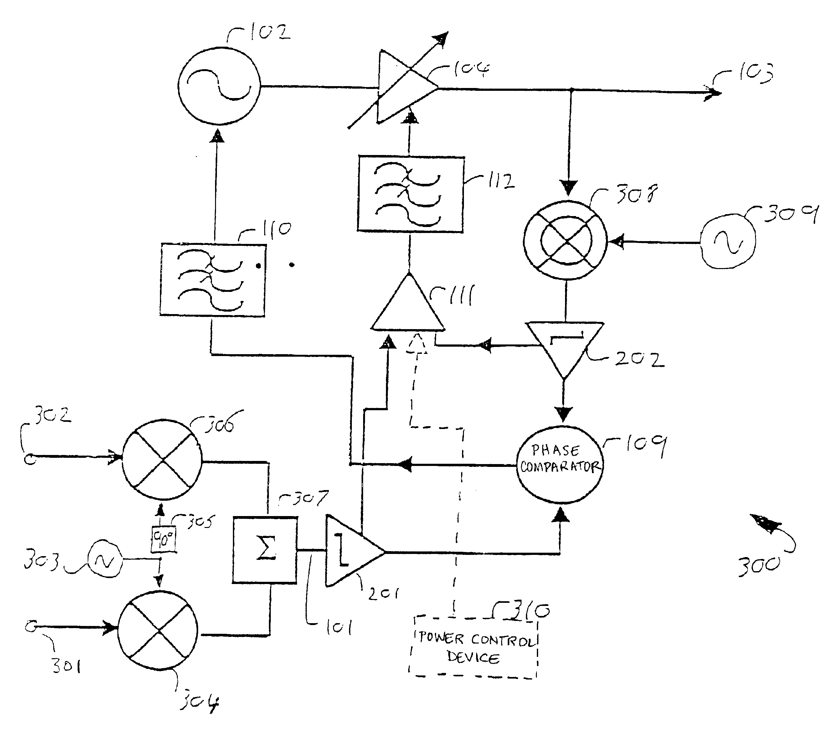
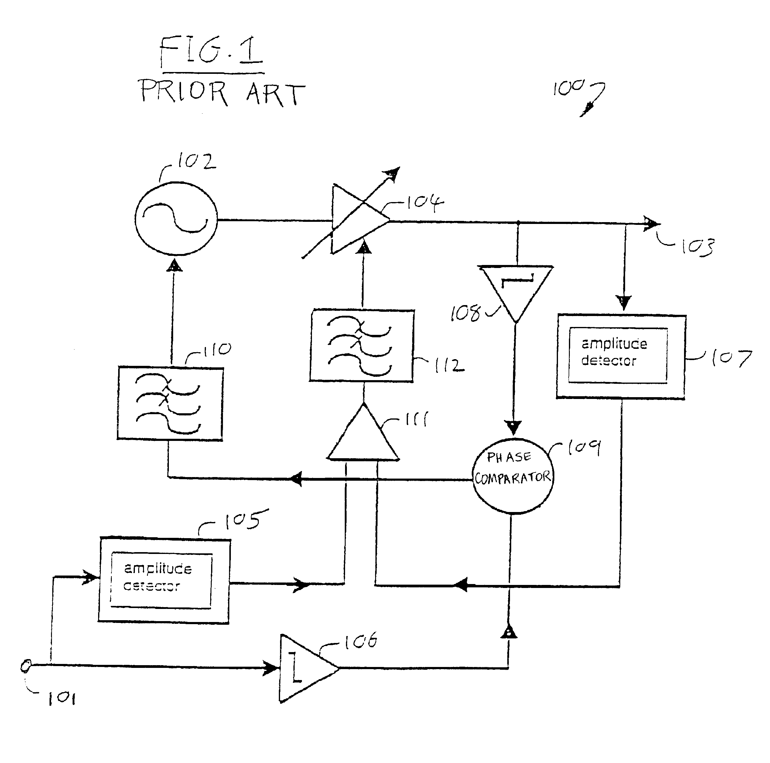
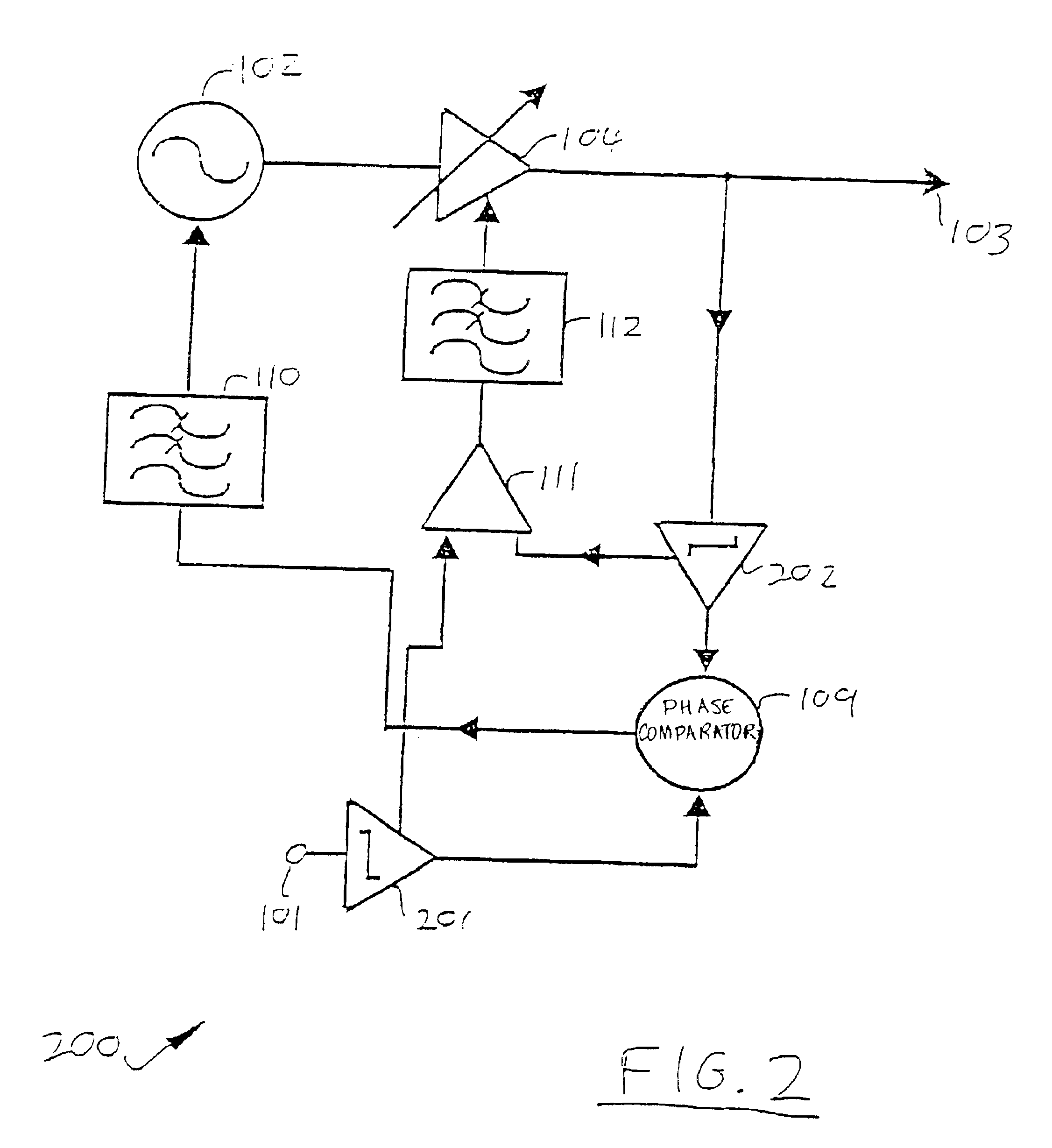
In FIGS. 2 and 4, certain reference numerals are the same as those used in FIG. 1 for like elements.

Referring to FIG. 2, a polar loop transmitter circuit arrangement 200 in accordance with the invention has, in place of the amplitude detectors 105, 107 an...


PUM


Abstract

A polar loop transmitter circuit arrangement includes a circuit input, a circuit output, a controllable signal source, a modulator connected between the signal source and the output, a first amplifier having its input connected to the circuit input, a second amplifier having its input connected to the circuit output, and a comparator. Each amplifier preferably includes respective amplitude detector and signal modifier portions connected in series between their respective inputs and outputs. An output of each of the amplifiers is connected to a respective input of the comparator, and an output of the comparator is connected to a control input of the modulator. The amplifiers may each be characterized by transfer functions that are generally logarithmic. Each amplifier's signal modifier portion may further include an analog-to-digital converter, a digital signal modifier, and a digital-to-analog converter. Additional signal mixer and/or phase comparison elements may also be incorporated into select embodiments of the subject polar loop transmitter technology.

Description

CROSS-REFERENCE TO RELATED APPLICATIONSThe present application claims priority to currently pending United Kingdom Patent Application number 0124332.8, filed on Oct. 10, 2001.STATEMENT REGARDING FEDERALLY SPONSORED RESEARCH OR DEVELOPMENTN / ABACKGROUND OF THE INVENTIONThe polar loop transmitter was first described by Gosling and Petrovic in Electronics Letters, 1979, 15 (10) pp 286-288. This was a development of the work of Kahn “Single Sideband Transmission by Envelope Elimination and Restoration,” Proc. IRE 1952, 40, pp 803-806. The basic scheme of the polar loop transmitter is shown in FIG. 1.Referring to FIG. 1, the transmitter 100 generally comprises an RF input 101 to which is applied in use an input signal, and a voltage controlled oscillator (VCO) 102. A signal output of the VCO 102 is fed via a controllable gain amplifier 104 to an RF output 103, to provide a modulated RF output signal. Similarly, the RF output 103 is connected both to a second amplitude detector 107 and to ...

Claims


Application Information

Patent Timeline
Patent Type & Authority Patents(United States)
IPC IPC(8): H03F1/02H03F1/06H03F1/32
CPCH03F1/0205H03F1/32H03F1/3282H03F1/3247H03F2201/3233
Inventor CHADWICK, PETER EDWARD
Owner INTEL CORP
Why Eureka
Try Eureka