Authentication techniques in a monitoring system

a monitoring system and authentication technique technology, applied in the direction of anti-theft devices, programs, instruments, etc., can solve the problems of ineffective monitoring, inconvenient monitoring, and the authentication scheme of signal transmission is too simple, so as to improve the ability to authenticate received transmissions

Inactive Publication Date: 2005-01-18
BI
View PDF30 Cites 79 Cited by
  • Summary
  • Abstract
  • Description
  • Claims
  • Application Information

AI Technical Summary

Benefits of technology

Accordingly, it is an object of the present invention to provide an improved electronic house arrest monitoring (EHAM) system that provides an improved ability to authenticate received transmissions as having come from a particular transmitter.

Problems solved by technology

For example, depending to some extent on remoteness of the place monitored and other circumstances, monitoring may not be effective with RF signal transmissions from the transmitter on the offender that occur only once every ten hours, but transmitting RF signals once every ten seconds may be superfluous for monitoring.
Unfortunately, such a system is easily fooled by an impostor transmitter that produces a similar bit in each transmission and which toggles such bit as well.
In other words, such a signal transmission authentication scheme is too simple.

Method used


Image

  • Authentication techniques in a monitoring system
  • Authentication techniques in a monitoring system
  • Authentication techniques in a monitoring system

Examples


second embodiment

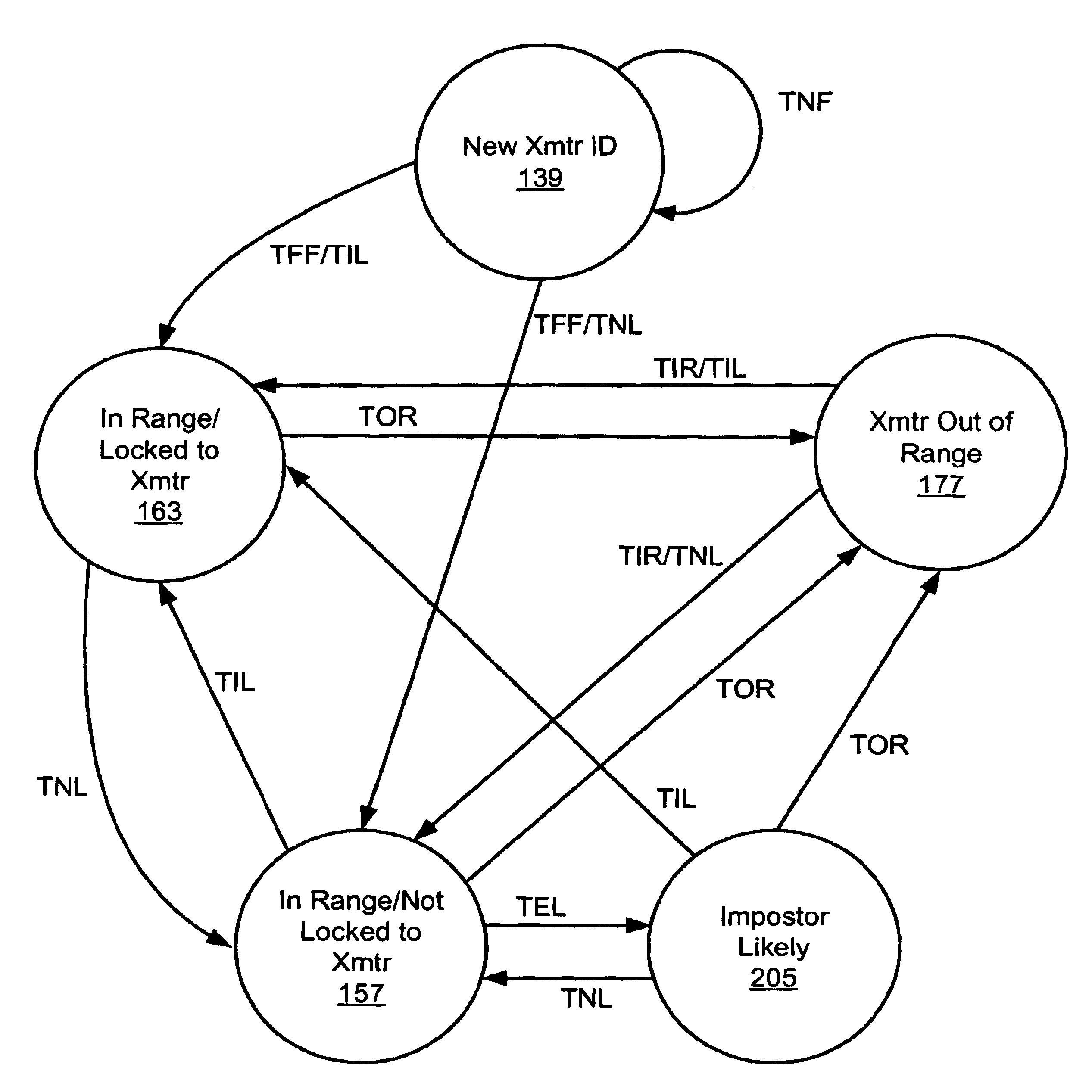
the present invention may differ from the first embodiment in that a portion of the data bits provided in each transmission 21 may provide information representative of the location of the current transmission 21 within the pseudo-random pattern of time intervals between consecutive transmissions 21. Thus, in such a second embodiment, once a single transmission 21 has been received, the microprocessor 80 in the receiver (FMD) 24 will be able to determine, thus know, exactly where such transmission 21 and associated time interval combination is in the pattern of pseudo-randomly varying time intervals, and it will not have to track several transmissions 21 in order to make the same determination. For this reason, by the time four valid transmissions 21 have been received so that the transmitter 22 can be determined to be in range, the receiver (FMD) 24 will already be locked onto the transmitter 22. The data bits relating to the location in the pattern do not necessarily have to be re...


PUM


Abstract

An Electronic House Arrest Monitoring (EHAM) system of the present invention includes a transmitter attached to a monitored offender and a receiver positioned in the vicinity of the desired monitoring location. The transmitter and the receiver each have a pattern stored or generated therein for determining the interval of time between signal transmissions and receptions. The pattern is pseudo-random to offer improved protection against imposter transmitters, in other words the time intervals are selected to be unequal and randomly varying but the pattern is repeated or cycled to allow continuing signal transmission by the transmitter. The transmitter transmits signals at varying time intervals according to this pattern, and the receiver authenticates signals it receives as coming from the monitored transmitter based on the expected time intervals from the pattern. The pattern may include any number of time intervals and, in one embodiment, includes more than one subpattern to extend the length of the repeat cycle to increase the difficulty of defeating the monitoring system. As further protection against imposter devices, the receiver may verify the signals based on information unique to the transmitter included in each signal. The receiver may further use the received signals and unique time interval patterns to determine a number of operating states, including New Transmitter ID Received, Transmitter In Range and Locked to Transmitter, Transmitter In Range and Not Locked, Transmitter Out of Range, and Imposter Likely. The monitoring system may also include a remote host computer linked to the receiver or receivers to enable these operating states to be monitored remotely by enforcement personnel.

Description

The present invention relates to techniques for authenticating or verifying transmissions from a particular transmitter to a receiver in a monitoring system, and in particular, to an authentication technique in a monitoring system that includes sequential transmissions from the transmitter at varying time intervals that vary in a pattern that is either known or determinable by both the transmitter and the receiver in a manner that enables the receiver to determine that signals it receives are authentic transmissions from the particular transmitter.BACKGROUND OF THE INVENTIONMonitoring systems in which a receiver monitors the presence or absence of a transmitter in the vicinity of the receiver are known in the art. Such monitoring systems have been used for monitoring persons or things in various applications, including monitoring criminal justice offenders under house arrest, monitoring locations of trucks or rail cars, monitoring movements of wild animals, and the like.Electronic h...

Claims


Application Information

Patent Timeline
Patent Type & Authority Patents(United States)
IPC IPC(8): G08B21/00G07C9/00G08B21/22H04L29/06H04M11/00
CPCG07C9/00111H04M11/007H04L63/126G08B21/22G07C9/28
Inventor MELTON, DONALD ALFREDWILBUR, TODD JAMES
Owner BI
Why Eureka
Try Eureka