Disk drive comprising a ratchet arm applied to a disk and disengaged through windage generated by the disk rotating

Inactive Publication Date: 2005-01-18
WESTERN DIGITAL TECH INC
View PDF5 Cites 50 Cited by
  • Summary
  • Abstract
  • Description
  • Claims
  • Application Information

AI Technical Summary

Benefits of technology

The present invention may also be regarded as a method of ratcheting rotation of a disk in a disk drive to help prevent the disk from rotating in a predetermined direction during shipping of the disk drive. A stopper is biased against a surface of the disk when the disk is not rotating, the disk is rotated to generate windage, and the windage is harnessed to disengage the stopper from the surface of the disk.

Problems solved by technology

During shipping, vibrations may cause the spindle bearings to oscillate in small back and forth motions causing the bearings to push through the lubricating and anti-rust oils until there is metal-on-metal contact.

Method used


Image

  • Disk drive comprising a ratchet arm applied to a disk and disengaged through windage generated by the disk rotating
  • Disk drive comprising a ratchet arm applied to a disk and disengaged through windage generated by the disk rotating
  • Disk drive comprising a ratchet arm applied to a disk and disengaged through windage generated by the disk rotating

Examples


Embodiment Construction

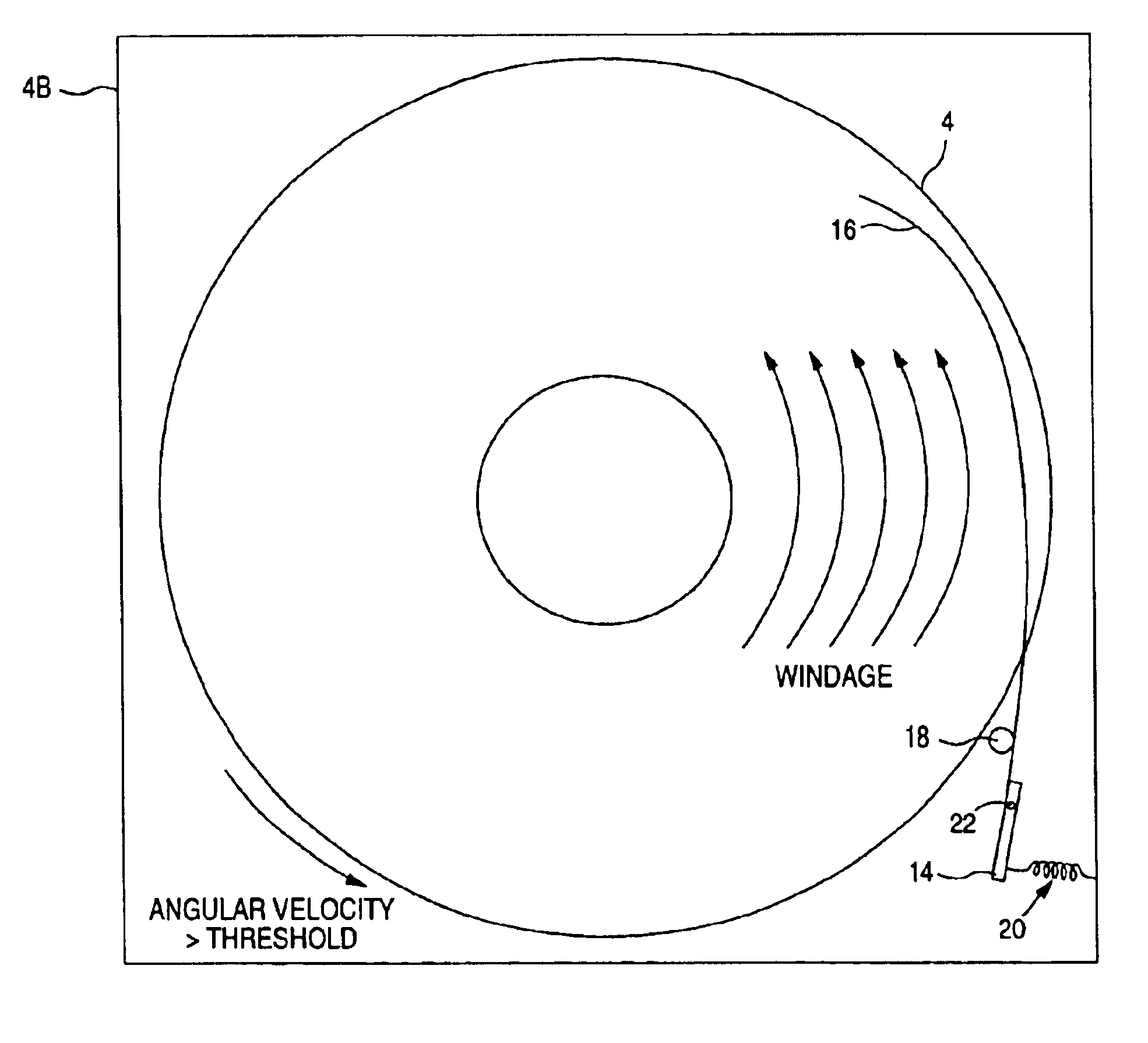
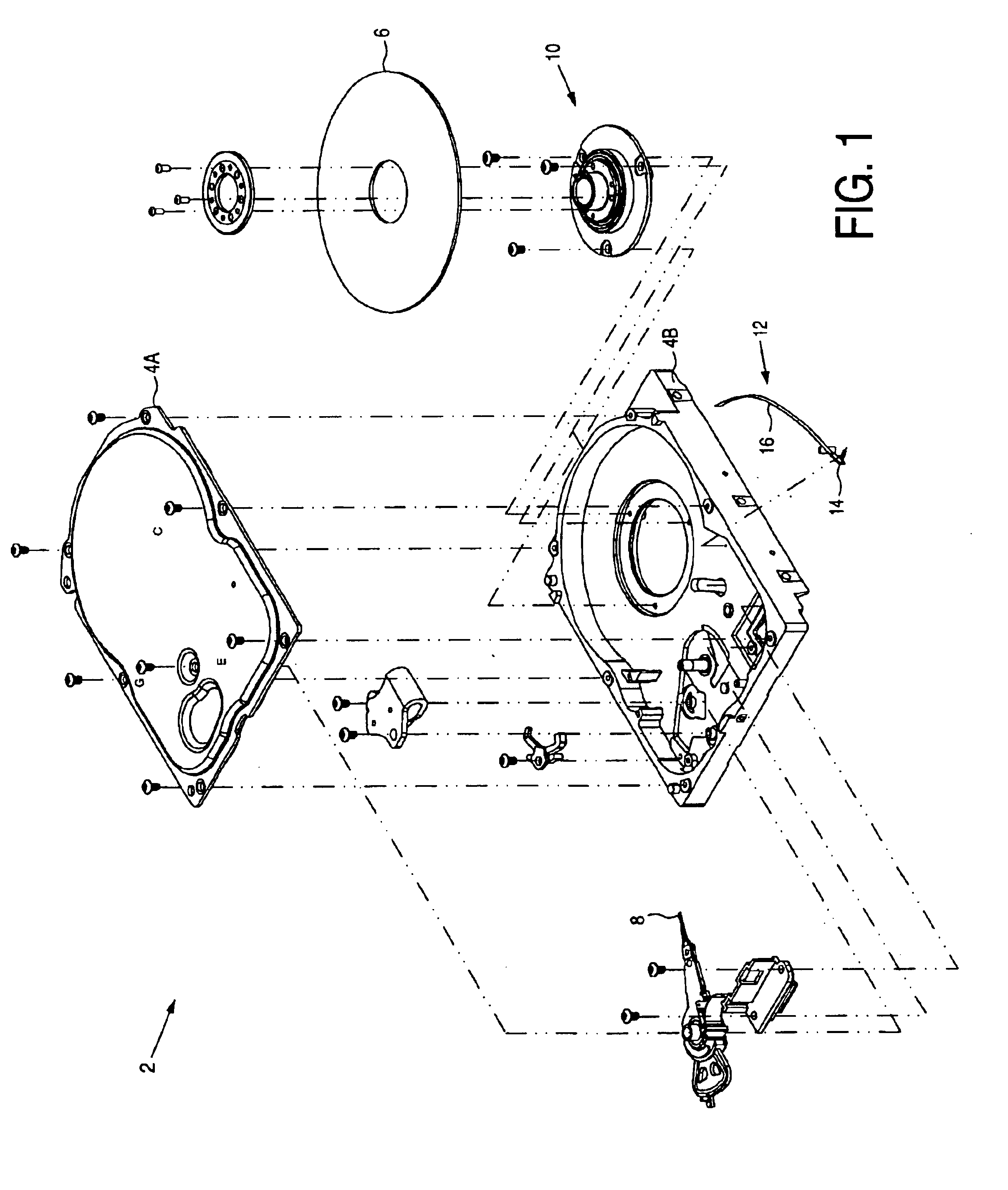
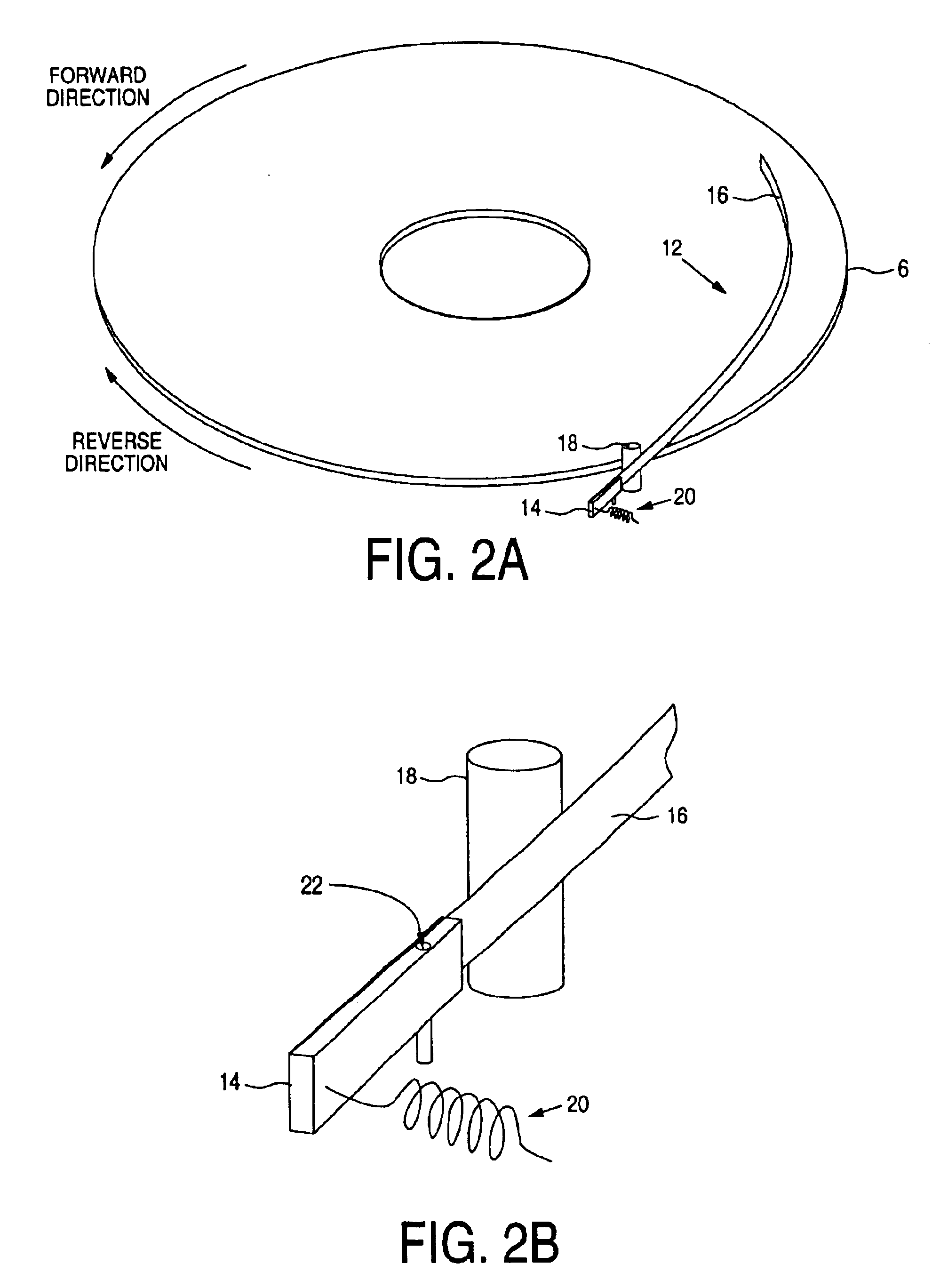
FIG. 1 is an exploded view of a disk drive 2 according to an embodiment of the present invention comprising an enclosure 4A and 4B, a disk 6, a head 8 actuated radially over the disk 6, a spindle motor 10 for rotating the disk 6, and a ratchet arm 12 for engaging a surface of the disk 6. The ratchet arm 12 comprises a base 14 end connected to the enclosure 4B of the disk drive and a wind vane 16 extending from the base end 14 adjacent the disk 6. The ratchet arm 12 disengages from the disk 6 due to windage pushing on the wind vane 16, the windage generated by the disk 6 rotating at an angular velocity greater than a threshold.

In the embodiment of FIG. 1, the wind vane 16 extends over a top surface of the disk 6. The wind vane 16 may also extend over a bottom surface of the disk, and in an alternative embodiment, rather than extend over the top or bottom surface of the disk 6 the wind vane 16 may be located near the outer periphery of the disk 6. In either embodiment, the windage gen...


PUM

PropertyMeasurementUnit
friction coefficientaaaaaaaaaa
angular velocityaaaaaaaaaa
biasing forceaaaaaaaaaa

Abstract

A disk drive is disclosed comprising an enclosure, a disk, a head actuated radially over the disk, a spindle motor for rotating the disk, and a ratchet arm having a base end connected to the enclosure of the disk drive and a wind vane extending from the base end adjacent the disk. The ratchet arm engages the disk when the disk is not rotating, and the ratchet arm disengages from the disk due to windage pushing on the wind vane, the windage generated by the disk rotating at an angular velocity greater than a threshold.

Description

BACKGROUND OF THE INVENTION1. Field of the InventionThe present invention relates to disk drives. More particularly, the present invention relates to a disk drive comprising a hub ratchet arm applied to a disk and disengaged through windage generated by the disk rotating.2. Description of the Prior ArtThe spindle motor within a disk drive typically employs high accuracy, low noise spindle bearings encased in lubricating and anti-rust oils. During shipping, vibrations may cause the spindle bearings to oscillate in small back and forth motions causing the bearings to push through the lubricating and anti-rust oils until there is metal-on-metal contact. The metal-on-metal contact creates micro spots of fretting corrosion which exacerbates acoustic noise and non-repeatable run-out (NRRO).There is, therefore, a need for a disk drive which minimizes metal-on-metal contact of the spindle bearings due to vibrations during shipping.SUMMARY OF THE INVENTIONThe present invention may be regarde...

Claims


Application Information

Patent Timeline
Patent Type & Authority Patents(United States)
IPC IPC(8): G11B33/08G11B5/60G11B25/04
CPCG11B5/60G11B33/08G11B25/043
Inventor BERDING, KEITH R.GUSTAFSON, JOHN R.
Owner WESTERN DIGITAL TECH INC
Why Eureka
Try Eureka