
Optical disk apparatus and focus control method thereof

a technology of optical disk and control method, which is applied in the direction of combination recording, data recording, instruments, etc., can solve the problems of affecting the sampling period of the feedback control system, the control system is oscillated, and the inability to obtain a control band with a high band

Inactive Publication Date: 2005-01-18
PANASONIC CORP
View PDF14 Cites 9 Cited by
  • Summary
  • Abstract
  • Description
  • Claims
  • Application Information

AI Technical Summary

Benefits of technology

With the foregoing in view, it is an object of the present invention to provide a disk apparatus and a focus control method thereof to improve the learning accuracy of a periodic disturbance along with the rotation of the disk.
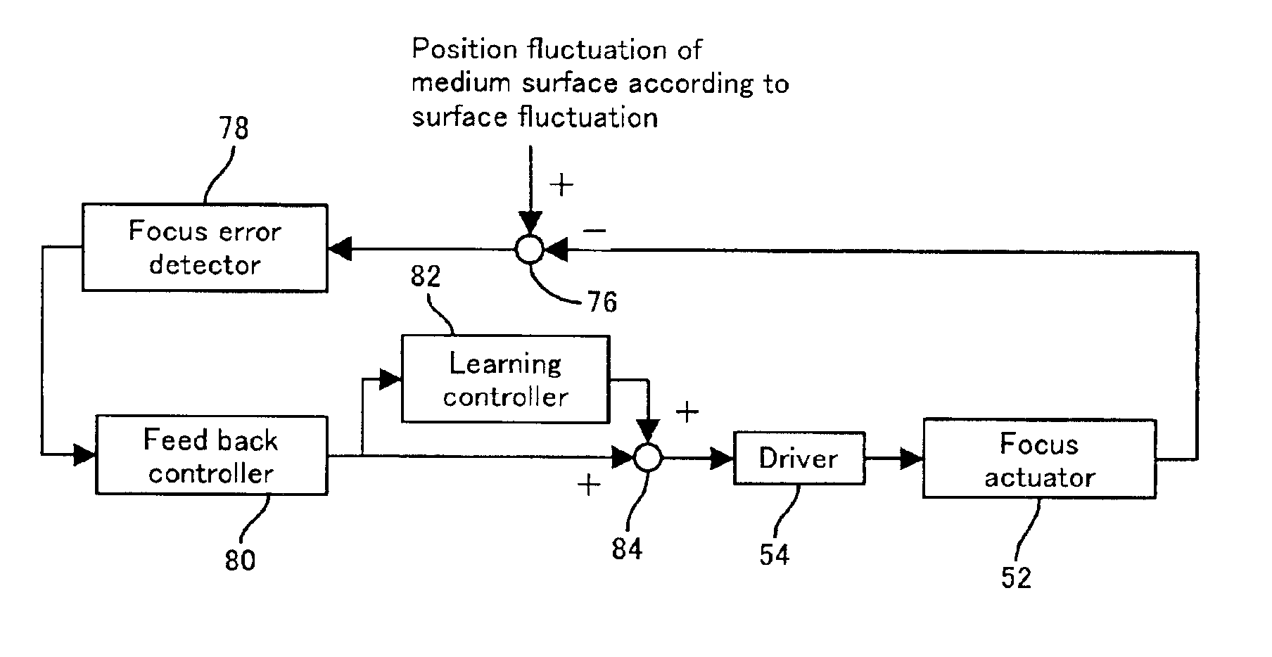
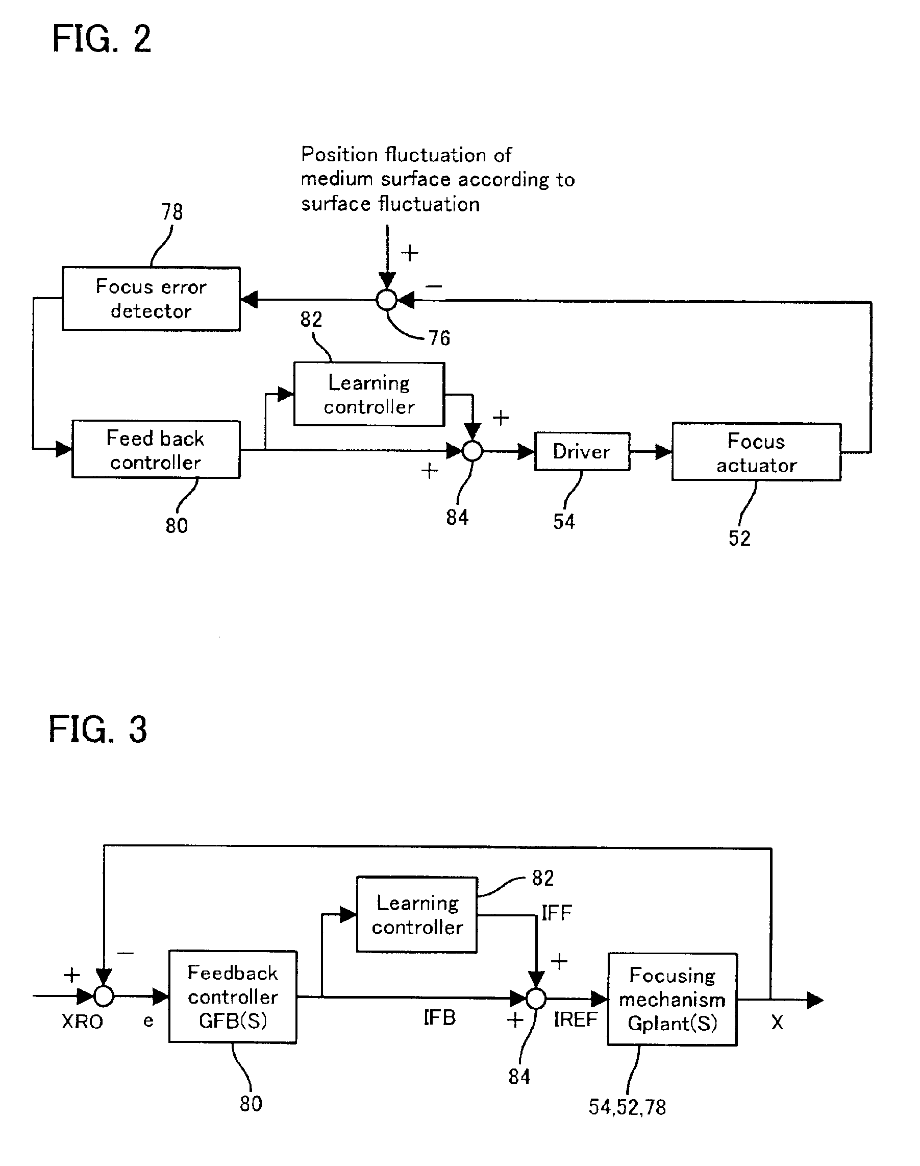
Also according to the present invention, the above mentioned learning control section samples signals which follow the focus error signal, updates a value of one of the memory cells, which is allocated to a time close to the sampling time, by the learning algorithm, and learns the unknown function, so that the unknown function can be efficiently learned even if the memory length is decreased, and the calculation amount can be decreased.

Problems solved by technology

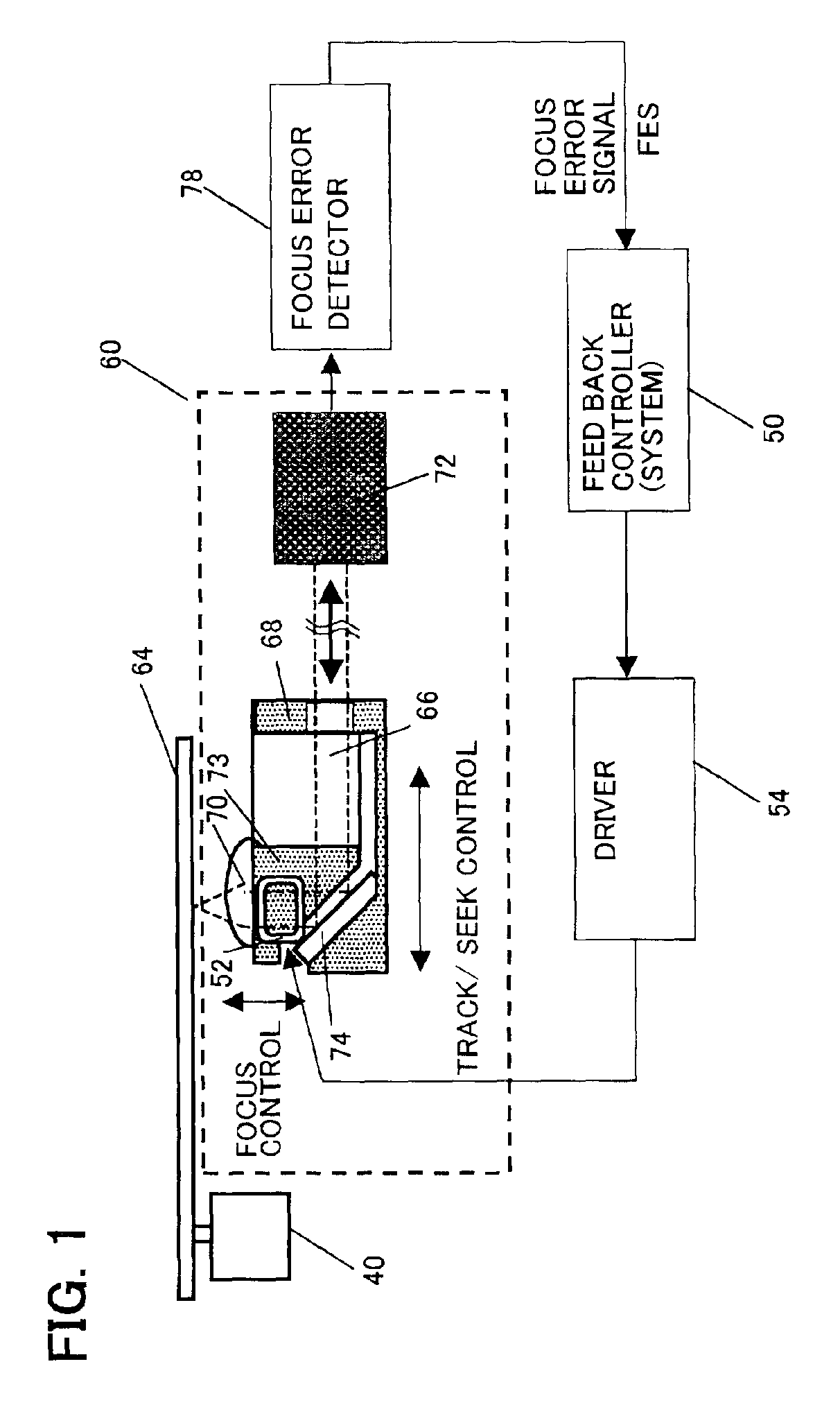
While, in the optical disk apparatus, the surface of the disk medium vibrates toward the focusing direction (a normal line direction of the disk surface) according to the rotation of the disk due to an error of a mechanical attachment of the spindle, an error of chuck between the spindle and the disk medium, and a curvature of the disk medium itself.
However, if only feedback control is performed, it is obstructed to obtain a control band with a high band, because a high order mechanical resonance and a light modulated component mix to the control system as disturbances.
If it is tried to expand unreasonably the control band, the problem occurs to decrease a phase margin, thereby the control system is oscillated.
In a disk unit, such as a magneto-optical disk unit, however, the sampling period of the feedback control system is relatively short.
In order to decrease the memory length, it is possible to set the dividing period of the repetitive control system to a multiple integer of the sampling period of the feedback control system, and skip the feedback information obtained at the sampling period, but learning an accurate feed-forward compensation signal is difficult since feedback information is not effectively utilized.

Method used


Image

  • Optical disk apparatus and focus control method thereof
  • Optical disk apparatus and focus control method thereof
  • Optical disk apparatus and focus control method thereof

Examples


first embodiment

In this first embodiment, further when Δtl is designed, the deigned value is obtained to subtract T / 2 from the designed value. By this, it can be prevented that the memory cell to be output is deviated from the memory cell to be updated to perform a stable convergence of the learning. That is, it is possible to make the timing relationship between the select timing of the updated memory cell and the select timing of the output memory cell to be consistent, and then to perform a proper adjustment by the time-lead compensation of Δtl to be considered the closed loop characteristic of the feedback control system which is a learning control object. Thereby the stable convergence of the learning can be performed.

[2] Calculating learning control system output value IFF;

When linear interpolation is executed on the two memory cell values defined by the time T interval, the output value is output according to the formula on a line passing through (ΔT, IFF)=(0, c^io1) and (ΔT, IFF)=(T, c^io2)...

second embodiment

[Second Embodiment of Feedback and Learning Control]

FIG. 10 is a diagram depicting the learning algorithm of the second embodiment of this invention, FIG. 11 is a diagram depicting the approximate function thereof, and FIGS. 12(A) to 12(E) are diagrams depicting the learning operation. In this embodiment, the way to select a memory cell to be updated, which is described in FIG. 6, is improved considering the way to output the linearly-interpolated value of two adjacent memory cells, so that efficient learning (efficient memory update) becomes possible, and learning time can be decreased. The effect is particularly high when high-speed learning is attempted with setting the learning gain high. Convergence errors of a waveform after convergence can also be decreased.

In the above mentioned first embodiment, in the case of t=3Ts, t=T (=4 Ts) where c^1 is allocated is closer in time, the approximate line (unknown) to the target can be more efficiently approached to update the value of c^...

third embodiment

[Third Embodiment of Feedback and Learning Control]

Now a case of simultaneously updating two memory cells will be described for each processing of DSP 50 with reference to FIG. 13 to FIG. 18.

2. Processing when two memory cells are simultaneously updated;

The third embodiment where two memory cells are simultaneously updated will be described next. In the present invention, a polygonal approximation by linearly connecting the heights of vertices stored in the memory cells is used, as shown in FIG. 8, and in the third embodiment, the nature of approximation by linear interpolation is considered more accurately so as to increase the speed and precision of the convergence of learning. Each processing of DSP 50 in the third embodiment will be described below.

A. Operation of feedback control system;

Just like the above mentioned case of updating a single memory cell, the focus error signal (FES) is sampled by the AD converter (not illustrated), and the feedback control operation, such as th...


PUM


Abstract

In a focus control for following a focus position of light beam to be radiated to an optical disk to an optical disk surface, the technique is for shorten the memory length in the learning controller. The learning controller is provided to a focus feedback control system and updates the memory comprised of N numbers of memory cells with a shorter sample period than a time obtained by dividing the time required for one rotation of the disk by N numbers and outputs the learning results in the memory with the shorter sample period.

Description

BACKGROUND OF THE INVENTION1. Field of the InventionThe present invention relates to a focus control method and an optical disk apparatus thereof for driving an objective lens so as to focus a light beam to a recording surface of an optical disk whereby maintaining a constant distance between the objective lens and the optical disk, especially to a focus control method and an optical disk apparatus thereof for calculating the control signal for suppressing the dislocation due to periodic disturbance, such as medium surface vibration by learning control, and executes feed-forward control in a control system to perform feedback control on a lens actuator so that the dislocation amount of the objective lens, with respect to the just focus position, becomes small (almost zero).2. Description of the Related ArtAn optical disk apparatus rotates an optical disk, such as a disk configuration and a card configuration, and radiates a light beam onto a recording surface of the optical disk to ...

Claims


Application Information

Patent Timeline
IPC IPC(8): G11B7/095G11B7/09G11B11/105
CPCG11B7/0956G11B11/10576
Inventor WATANABE, ICHIRO
Owner PANASONIC CORP
Learn More