
Mammography apparatus and method

a technology of mammography and apparatus, applied in mammography, medical science, diagnostics, etc., can solve problems such as source of ambiguity, and achieve the effect of reducing ambiguities

Inactive Publication Date: 2005-01-18
GE MEDICAL SYST GLOBAL TECH CO LLC
View PDF4 Cites 24 Cited by
  • Summary
  • Abstract
  • Description
  • Claims
  • Application Information

AI Technical Summary

Benefits of technology

There is consequently a need for mammography apparatus and method that allows images to be taken simply, while reducing ambiguities arising from tissue superimposition.

Problems solved by technology

When examining a dense breast or one that includes numerous fibrous structures, tissue superimposition when taking shots is a source of ambiguity in their interpretation.

Method used


Image

  • Mammography apparatus and method
  • Mammography apparatus and method

Examples


Embodiment Construction

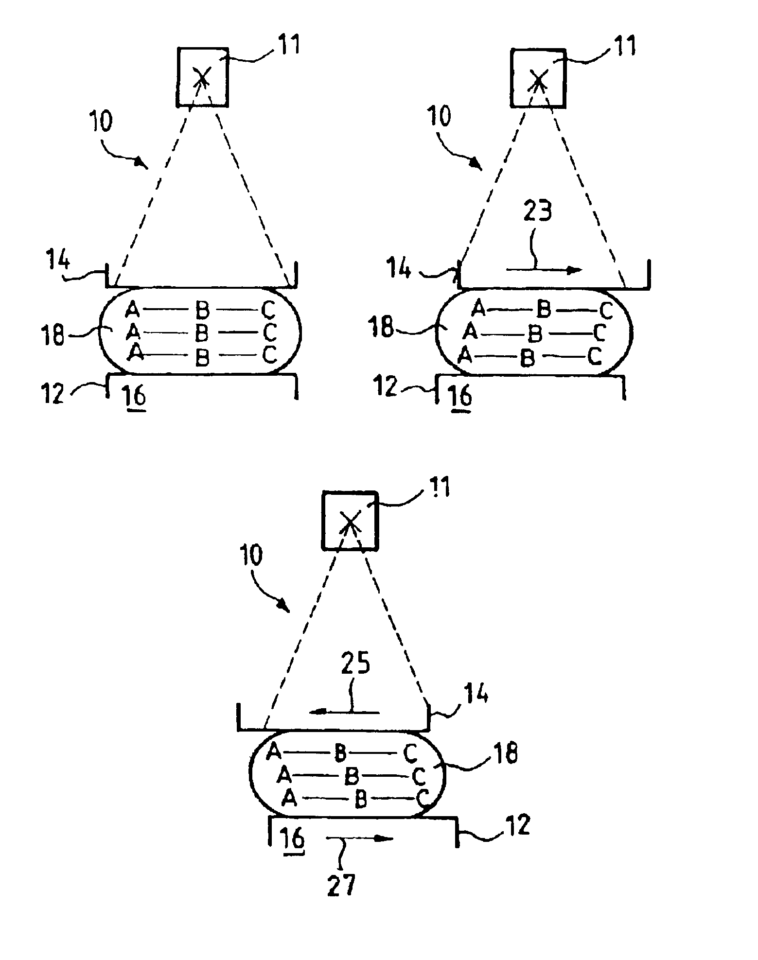
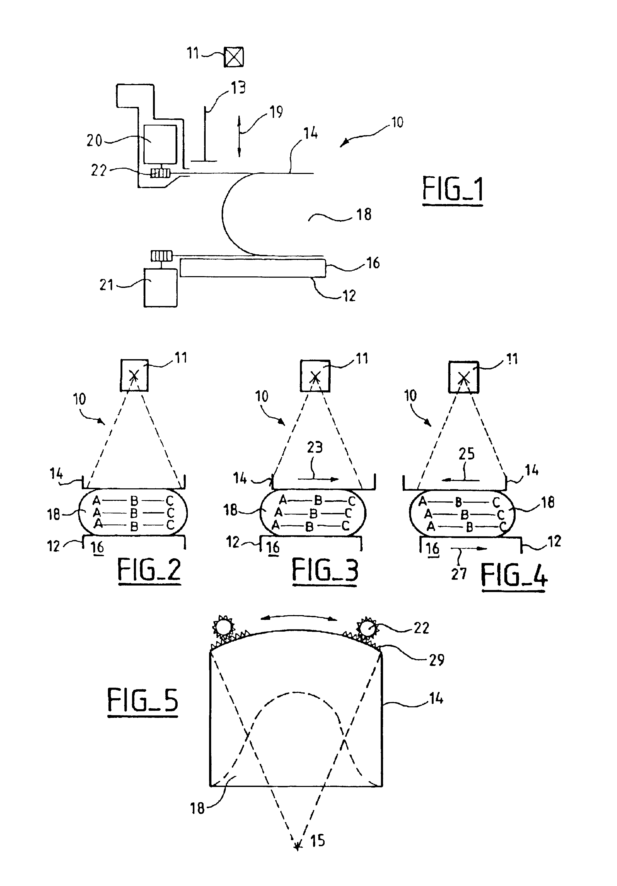
With reference to the drawings, a mammography apparatus and method according to one embodiment of the invention is shown. FIG. 1 is a diagrammatic side view showing the apparatus 10 in a breast compression position. The apparatus comprises a tube 11 delivering X-rays in a propagation direction, an image receiver 12 and a compression paddle 14 applied to the contour of breast 18. Image receiver 12 is adapted to receive radiation from the tube. Image receiver 12 has an edge 16 for contact with the patient. Compression paddle 14 is between the tube 11 and image receiver 12. The paddle can be moved up and down parallel to the direction of propagation of the X-rays. The compression paddle allows a patient's breast to be compressed against image receiver 12 when images are being taken. The mammography apparatus also comprises means 13 for maintaining compression paddle 14 in a compression position, along the direction of propagation of the radiation. In this compression position, compress...


PUM


Abstract

A mammography apparatus and method having an X-ray tube, an image receiver, the image receiver having one edge in contact with a patient, a compression paddle between the tube and the receiver, able to be moved up and down parallel to a direction of propagation of the X-rays, means for keeping the compression paddle in position in the radiation propagation direction, the compression paddle, in its compression position, being movable in at least one direction perpendicular to the direction of X-ray propagation and parallel to the contact edge of the image receiver. This allows a patient's breast to be rolled and presented to the image receiver in different positions thereby reducing ambiguities in possible detection of a lesion due to layers of tissue overlapping when images are taken.

Description

CROSS-REFERENCE TO RELATED APPLICATIONSThis application claims the benefit of a priority under 35 USC 119 to French patent application No. 01 01318 filed Sep. 25, 2001 the entire contents of which are hereby incorporated by reference.BACKGROUND OF THE INVENTIONA mammography apparatus and method enables breasts of patients to be examined using X-rays. An image or images is acquired using an image receiver comprising, for example, a photographic plate or digital sensing means. When taking the images, the patient's breast is held against the image receiver by means of a compression paddle. The compression paddle presses the breast against a receiver, compressing it in the direction of propagation of the X-rays. Examinations practised using such apparatus comprise taking cranio-caudal and lateral views. Cranio-caudal views are taken by irradiating the breast from above so as to obtain a view thereof in an axis extending from the patient's head to her feet. A side view is taken by irradi...

Claims


Application Information

Patent Timeline
IPC IPC(8): A61B6/00A61B6/04
CPCA61B6/502A61B6/0414A61B6/466
Inventor RICK, ANDREASMULLER, SERGESALADIN, JEAN-PIERRE
Owner GE MEDICAL SYST GLOBAL TECH CO LLC
Learn More