Site profile based control system and method for controlling a work implement

a control system and work implement technology, applied in the direction of process and machine control, vehicle position/course/altitude control, instruments, etc., can solve the problems of ineffective manual control of a work implement, such as a bulldozer blade, and operators do not have direct ground, and speed feedback is not availabl

Active Publication Date: 2005-01-18
CATERPILLAR INC
View PDF54 Cites 143 Cited by
  • Summary
  • Abstract
  • Description
  • Claims
  • Application Information

AI Technical Summary

Benefits of technology

In one aspect of the present invention, an automatic control system for a work machine is provided. The work machine operates at a work site containing material. The automatic control system includes a positioning system, a site model, and a controller. The positioning system determines a relative location of the work machine within the work site and produces a...

Problems solved by technology

Often manual control of a work implement, such as a bulldozer blade, is inefficient, particularly over a period of time as the operator tires.
Operators do not have direct ground, speed feedback and they cannot see the load on the blade.
The use of slip as a feedback mechanism is inefficient because slippage does not occur until productivity has already been lost.
Difficulties are often encountered in the control of the work implement when different ground profiles are encountered by the work machine.
However, the prior automatic control systems do not adequately control the blade posi...

Method used


Image

  • Site profile based control system and method for controlling a work implement
  • Site profile based control system and method for controlling a work implement
  • Site profile based control system and method for controlling a work implement

Examples


Embodiment Construction

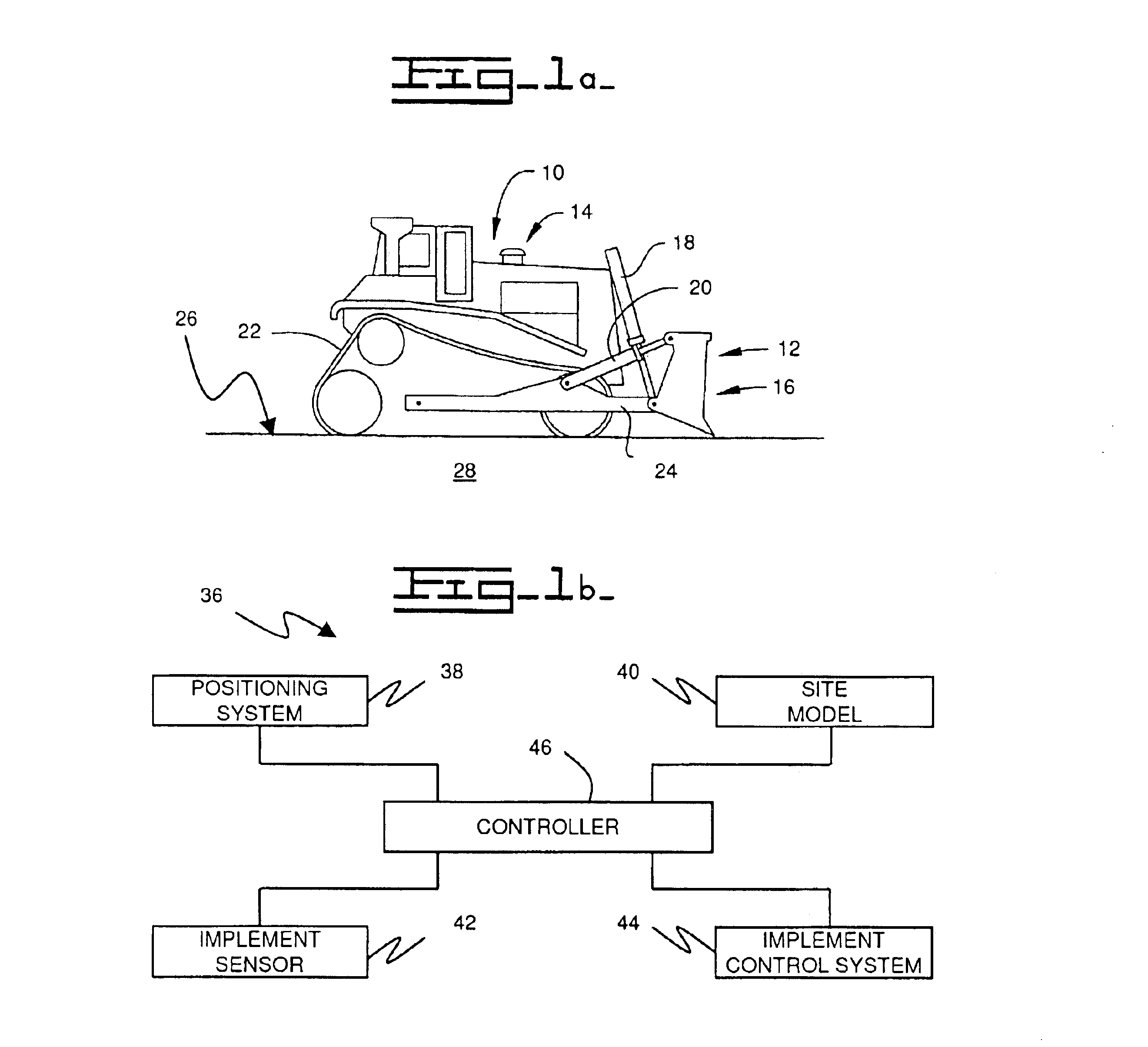
With reference to the drawings, FIG. 1 shows a planar view of a work machine 10 having a work implement 12. For example, the work machine 10 may be an earthmoving machine and the work implement may be work implement 12 utilized to move earth or soil.

For illustrative purposes the work machine 10 shown is a track-type tractor 14 and the work implement 12 shown is a bulldozer blade or bulldozer 16. While the invention is described using the tractor 14 and the bulldozer blade 16, it is intended that the invention also be used on other types of work machines 10 and work implements 12 such as construction or agricultural machines and earthmoving machines, e.g., a wheel loader or a track loader. The tractor 14 includes hydraulic lift actuators 18 for raising and lowering the blade 16 and hydraulic tilt actuators 20. Although not shown in FIG. 1, the tractor 14 preferably includes two lift actuators 18 and two tilt actuators 20, one on each side of the bulldozer blade 16. As shown in FIG. 1...


PUM


Abstract

An automatic control system for a work machine includes a positioning system, a site model, and a controller. The work machine operates at a work site containing material to be operated on by the work machine. The positioning system determines a relative location of the work machine within the work site and produces a machine position signal. The site model contains data related to a condition of the material. The controller is coupled to the site model, receives the machine position signal and determines a current condition of the material as a function of the position signal and the site model, and controls the work machine as a function of the current condition of the material.

Description

DESCRIPTION1. Technical FieldThe present invention relates generally to an apparatus and method of controlling a work machine, and more particularly, to an apparatus and method for controlling a work machine as a function of material conditions.2. BackgroundIt is advantageous for a work implement of a work machine such as a track / wheel tractor to be operated in a manner that results in the greatest productivity. Often manual control of a work implement, such as a bulldozer blade, is inefficient, particularly over a period of time as the operator tires.Maximum productivity can be achieved by maximizing the “draft power” of the work machine. Draft power is the rate of actual useful work being done in moving the soil and is defined as the product of the draft force of the work implement and the ground speed of the work machine.In the example of a tractor, draft force is the force on the blade. Maximum draft power is reached when the tractor is moving at optimum ground speed commensurat...

Claims


Application Information

Patent Timeline
IPC IPC(8): E02F3/76E02F3/84
CPCE02F3/847
Inventor STRATTON, KENNETH LEEHENDERSON, DANIEL E.
Owner CATERPILLAR INC
Why Eureka
Try Eureka