Satiation devices and methods

a technology applied in the field of satiation devices and methods, can solve problems such as removal and needing removal

Inactive Publication Date: 2005-01-25
BOSTON SCI SCIMED INC
View PDF54 Cites 467 Cited by
  • Summary
  • Abstract
  • Description
  • Claims
  • Application Information

AI Technical Summary

Benefits of technology

A satiation device utilizing principles of the present invention includes a tubular pouch positionable at the gastro-esophageal junction. The pouch has a proximal opening for receiving ingested food from the esophagus, and a distal opening for re...

Problems solved by technology

However, known complications are present with each of these procedures and more successful options are desire...

Method used


Image

  • Satiation devices and methods
  • Satiation devices and methods
  • Satiation devices and methods

Examples


Embodiment Construction

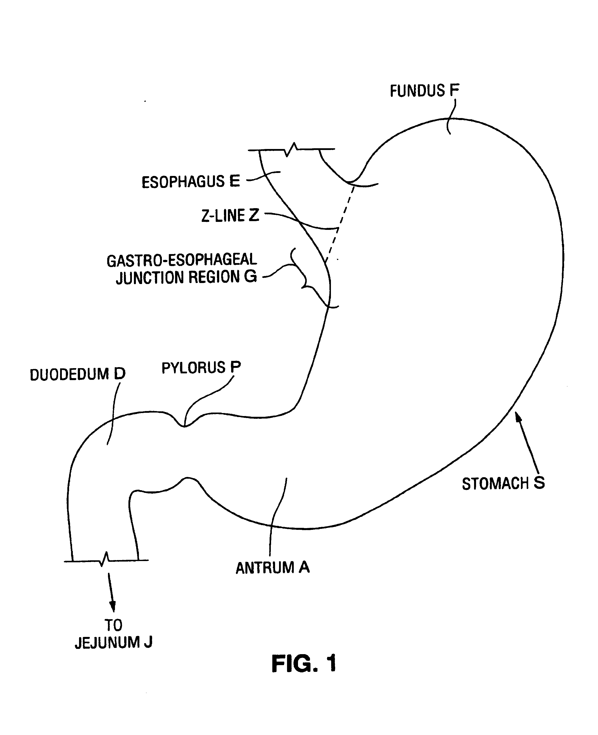
An anatomical view of a human stomach S and associated features is shown in FIG. 1. The esophagus E delivers food from the mouth to the stomach S. The z-line or gastro-esophageal junction Z is the irregularly-shaped border between the thin tissue of the esophagus and the thicker tissue of the stomach wall. The gastro-esophageal junction region G is the region encompassing the distal portion of the esophagus E, the z-line, and the proximal portion of the stomach S.

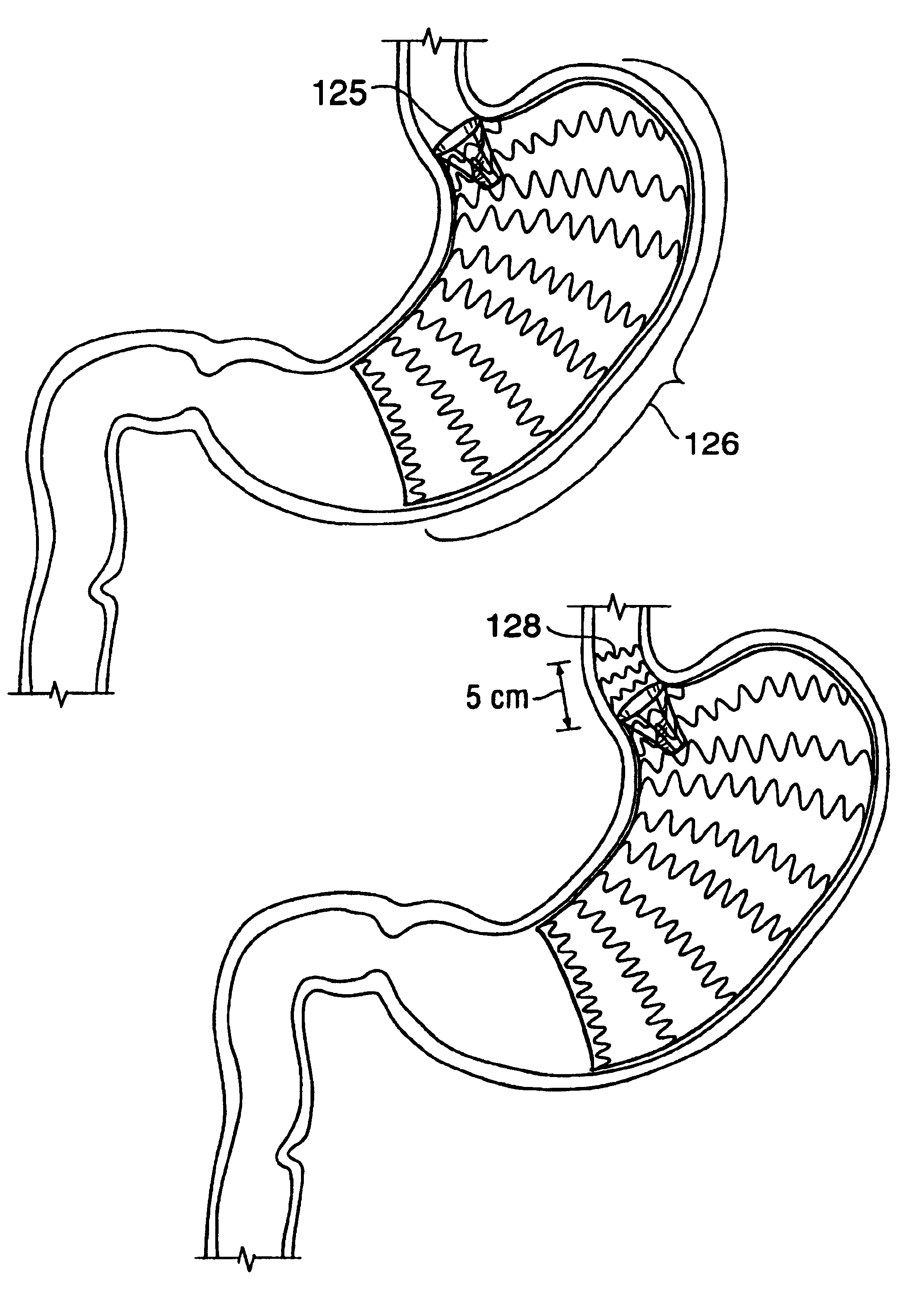
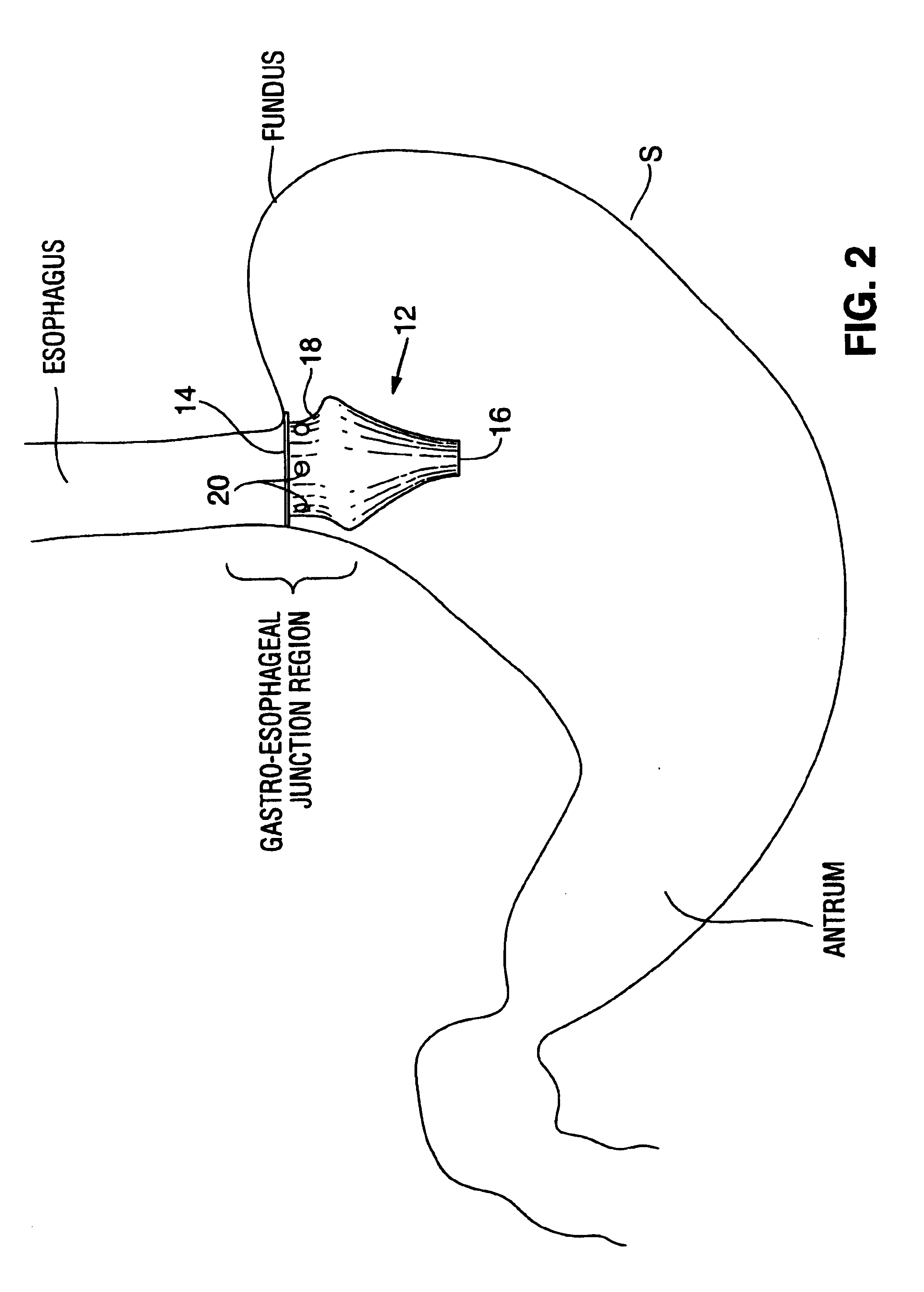
Various embodiments of satiation devices are described herein. Many of these devices include a pouch or funnel positioned at the gastro-esophageal junction region so as to form a small reservoir which collects masticated food from the esophagus—thereby limiting the amount of food that can be consumed at one time. Over time the food within this reservoir descends into the stomach through a distal opening in the pouch. The pouch may optionally include a tubular extension positionable within the esophagus to facilitate flow of...


PUM


Abstract

A device for inducing weight loss in a patient includes a tubular prosthesis positionable at the gastro-esophageal junction region, preferably below the z-line. In a method for inducing weight loss, the prosthesis is placed such that an opening at its proximal end receives masticated food from the esophagus, and such that the masticated food passes through the pouch and into the stomach via an opening in its distal end.

Description

FIELD OF THE INVENTIONThe present invention relates generally to the field of devices and methods for achieving weight loss in humans, and specifically to the use of devices implantable within the human stomach for controlling feelings of hunger.BACKGROUND OF THE INVENTIONVarious medical approaches are used for controlling obesity. These approaches include diet, medication, and surgical procedures. One of the more successful surgical procedures is the vertical banded gastroplexy or the proximal gastric pouch with a Roux-en-Y anastomosis that shunts food from the proximal region of the stomach into the intestine, thereby minimizing absorption of food into the bloodstream. However, known complications are present with each of these procedures and more successful options are desired.Other alternatives include implantation of gastric balloons that prevent overeating by occupying volume within the stomach. Unfortunately, gastric balloons can migrate down the GI tract, causing obstruction...

Claims


Application Information

Patent Timeline
IPC IPC(8): A61F2/04A61F5/00A61F2/00A61F2/06A61F2/24A61B17/00
CPCA61F2/04A61F5/0076A61F5/0089A61F2/07A61F2/24A61F2250/0067A61F2002/045A61F2002/067A61F2002/8483A61F2250/0039A61F2002/044
Inventor STACK, RICHARD S.GLENN, RICHARD A.ATHAS, WILLIAM L.WILLIAMS, MICHAEL S.
Owner BOSTON SCI SCIMED INC
Why Eureka
Try Eureka