
Compressed air pistol with blowout nozzle

Inactive Publication Date: 2005-01-25
MASSON LUCIEN
View PDF14 Cites 3 Cited by
  • Summary
  • Abstract
  • Description
  • Claims
  • Application Information

AI Technical Summary

Benefits of technology

A primary purpose of this invention is to improve upon a compressed air nozzle of the type defined above so that it meets the required or recommended safety standards and occupational safety regulations and guarantees easier handling at a much lower production cost. The invention also enables making appropriate pressure measurements. A preferred use of the compressed air nozzle of the invention is for it to be designed as a blow-out and cleaning nozzle (gun).
In another alternative embodiment, an air-reducing valve may be omitted. A connection sleeve is inserted into the system sleeve and together with a clamping piece it serves to connect and support a compressed air hose for supplying the compressed medium. Here again, the compressed air hose is inserted between the connection sleeve and the clamping piece, thus maintaining the advantages of low weight, low cost manufacture, low space requirement, self-sealing effect and thus also improved handling. The outlet valve is preferably designed as a tilt valve, with the hose socket enclosing the tilt valve.

Problems solved by technology

However, the systems available so far on the market, especially the blow-out guns, entail safety risks when used improperly.
When blowing out a workpiece without using safety goggles, eye injuries may occur due to blowback of chips and particles of dirt.
Furthermore, it occurs every so often that such blowout guns are used against people either as a joke or to clean their work clothes, which thus results in painful wounds on the skin or intestinal rupture to the abdomen.
Such pressure reducing valves are connected between the blow-out gun and the high-pressure hose so that the entire device becomes rather heavy and difficult to handle.
It has generally been complicated and expensive to perform the pressure measurement at the point of use and therefore it is rarely done.

Method used


Image

  • Compressed air pistol with blowout nozzle
  • Compressed air pistol with blowout nozzle
  • Compressed air pistol with blowout nozzle

Examples


Embodiment Construction

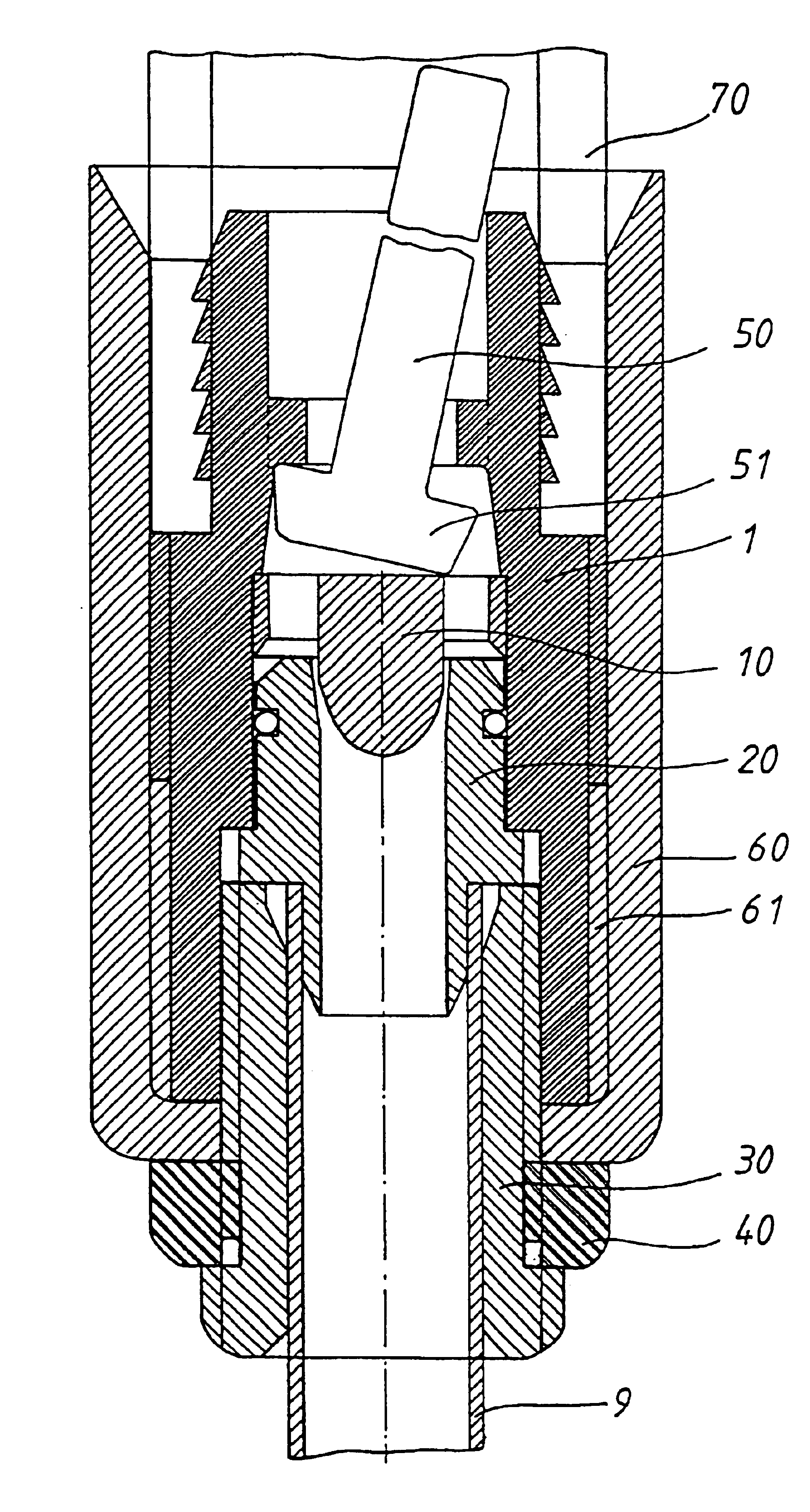
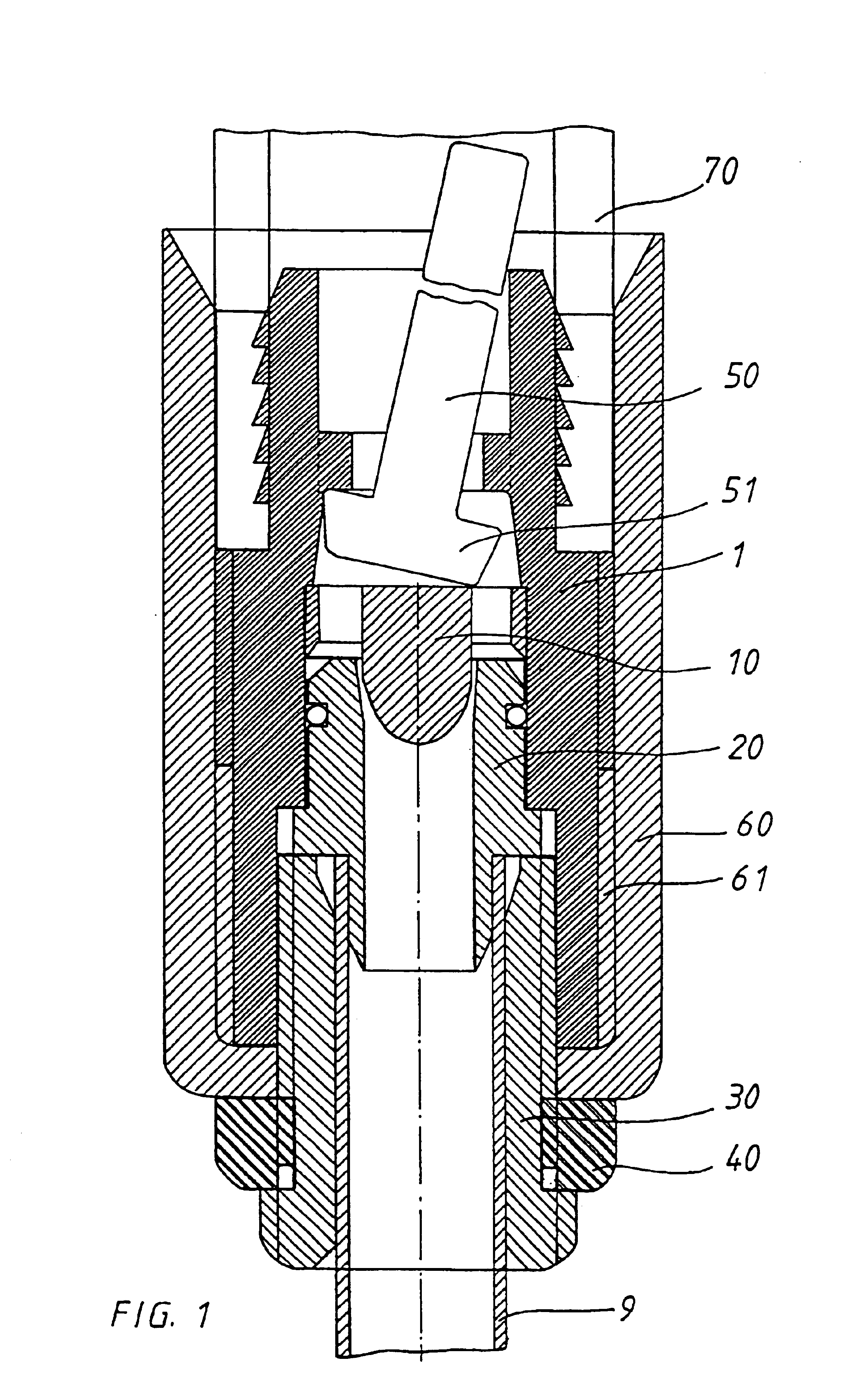
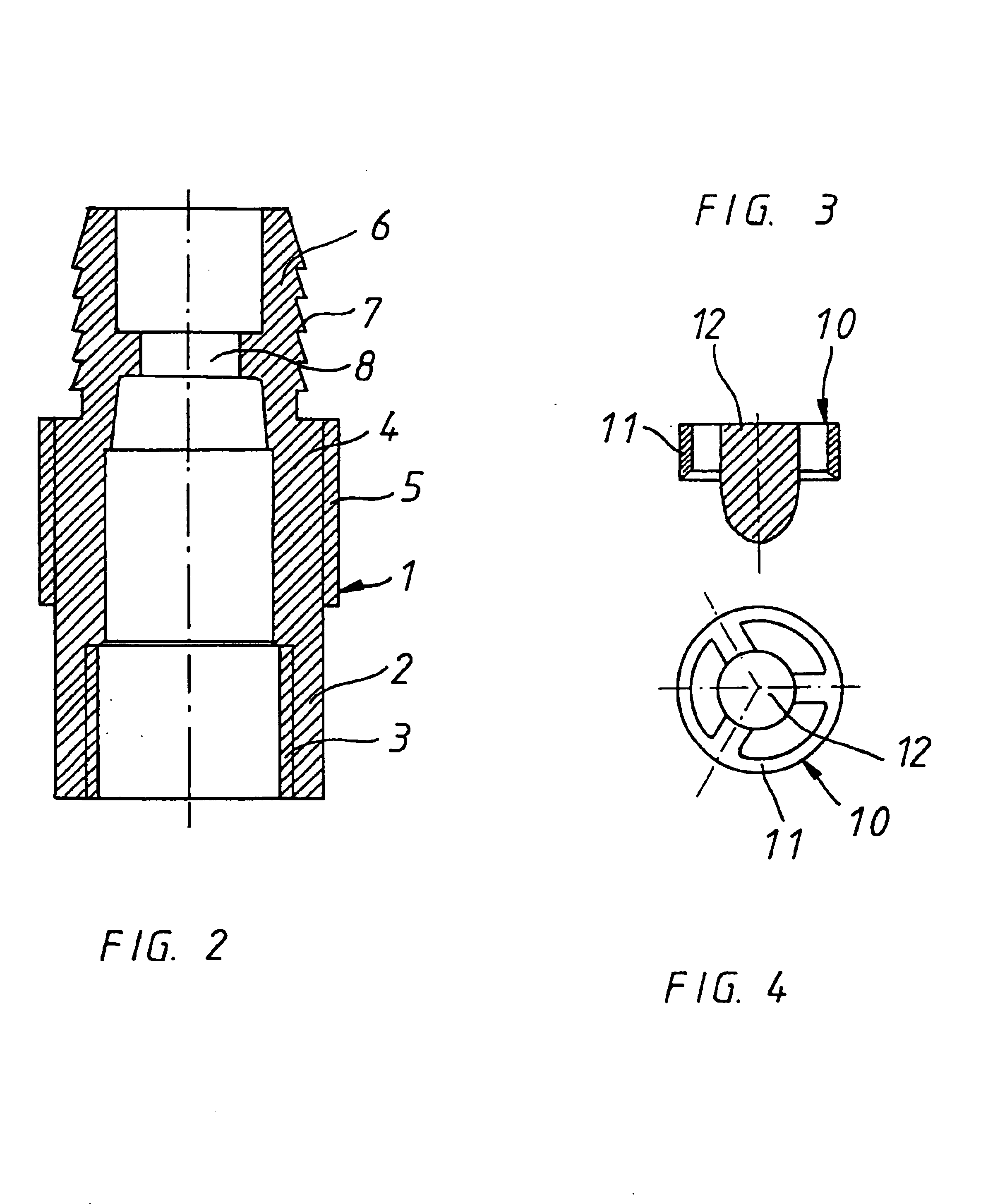
With reference now to the drawing, FIG. 1 shows the compressed air nozzle of the invention, shown here as a blow-out gun, and includes a system carrier consisting of system carrier or sleeve 1 which accommodates or holds all the components. According to FIG. 2, the system sleeve consists of lower section 2 which is provided with inside thread 3, middle section 4 which has hexagon socket 5, and upper section 6 with outer gearing 7 and / or an outer ribbing. An outside thread is also conceivable. In upper section 6 is a passage constriction in the form of a borehole 8. A chamber into which tilt valve 50 is inserted (see FIG. 8) is formed beneath borehole 8. The valve shaft projects through borehole 8 downstream beyond upper section 6 of system sleeve 1. When the valve is closed, valve cover or disk 51 is supported on a ring flange, which forms the borehole, thus forming a seal.

As shown in FIGS. 3 and 4, insert 10 having sleeve 11, which is inserted into system sleeve 1 with an accurate ...


PUM


Abstract

A pressurized fluid nozzle having a system carrier with a hose connection for supplying a pressurized medium and an outlet valve having at least one outlet nozzle. The system carrier is designed to accommodate an integrated, adjustable pressure-reducing valve. Furthermore, the system carrier has a system sleeve and a hose socket, which is connected to it, whereby a compressed air shield and / or a connection for a pressure gauge and / or a protection against accidental contact is / are integrated into the hose socket. In a preferred embodiment, components of the blow-out gun also serve at the same time to connect and support the hose and / or the finger guard and / or the extension tube for supplying the pressurized medium, and these components together with the hose can be removed from the system carrier.

Description

BACKGROUND OF THE INVENTION1. Field of the InventionThis invention relates to pressurized fluid nozzle, and more particularly to a nozzle assembly having an adjustable pressure reducing valve and operator safety features.2. Discussion of Related ArtCompressed air nozzles are well known from the related art, in particular for their use as blow-out guns. The blow-out guns used up to now have consisted of a system carrier, for example, which may be connected to a high pressure hose by means of a hose connection for supplying a pressurized medium. Furthermore, a manually or automatically operated outlet valve is also provided, whereby when this valve is operated, the pressurized medium flows out through an outlet nozzle or into a working machine to be activated to work. However, the systems available so far on the market, especially the blow-out guns, entail safety risks when used improperly. When blowing out a workpiece without using safety goggles, eye injuries may occur due to blowba...

Claims


Application Information

Patent Timeline
IPC IPC(8): B08B5/02B05B1/30B05B1/00B05B9/01
CPCB05B1/005B08B5/02B05B1/3013Y10T137/613
Inventor MASSON, LUCIEN
Owner MASSON LUCIEN
Learn More