Trailer landing gear

a technology of landing gear and trailer, which is applied in the direction of domestic objects, vehicle maintenance, shaping building parts, etc., can solve the problems of not allowing the switch of landing gears in the gear box assembly, the difficulty of assembling the gear assembly used to raise and lower the legs of the landing gear, and the inability of the truck operator to raise or lower a load in high gear, etc., to achieve the effect of simple construction, simple, effective and inexpensiv

Inactive Publication Date: 2005-01-25
JOST WERKE
View PDF62 Cites 41 Cited by
  • Summary
  • Abstract
  • Description
  • Claims
  • Application Information

AI Technical Summary

Benefits of technology

Another objective of the present invention is to provide a landing gear assembly having a tube and nut configuration that strengthens the landing gear when the landing gear is in an extended position.
A further objective of the prese

Problems solved by technology

In practical terms, this means that the truck operator cannot raise or lower a load in high gear.
However, if the semitrailer was left on a relatively unstable surface such as soft ground or blacktop, the semitrailer legs sometimes sink into the ground under the load of the trailer between the drop off and pickup times. If this is the case, or if a higher tractor is employed, the operator must further extend the legs to raise the trailer to provide sufficient clearance between the ground and the kingpin.
One of the problems with existing semitrailer landing gear is that the gear box or gear ho

Method used


Image

  • Trailer landing gear
  • Trailer landing gear
  • Trailer landing gear

Examples


Embodiment Construction

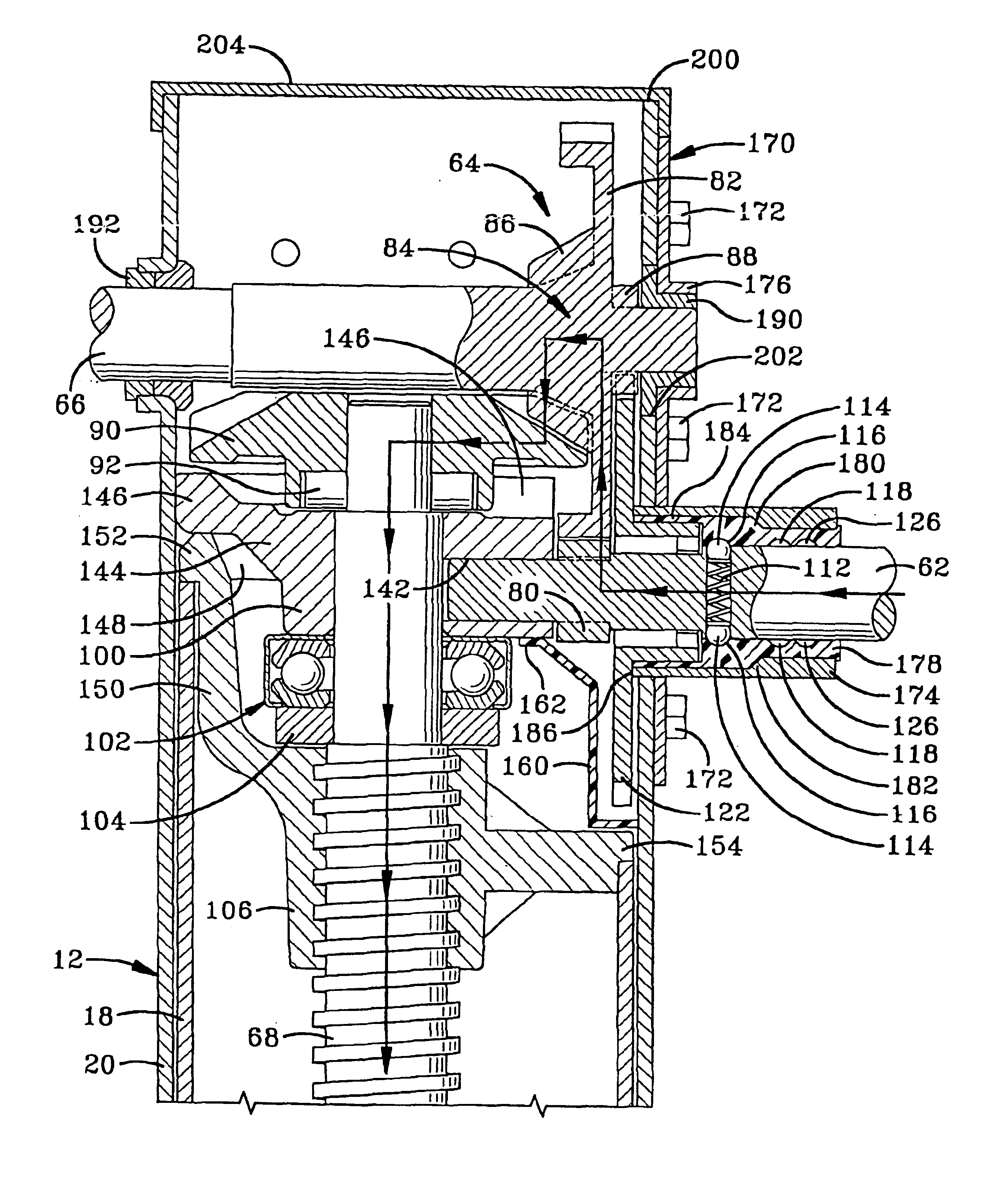
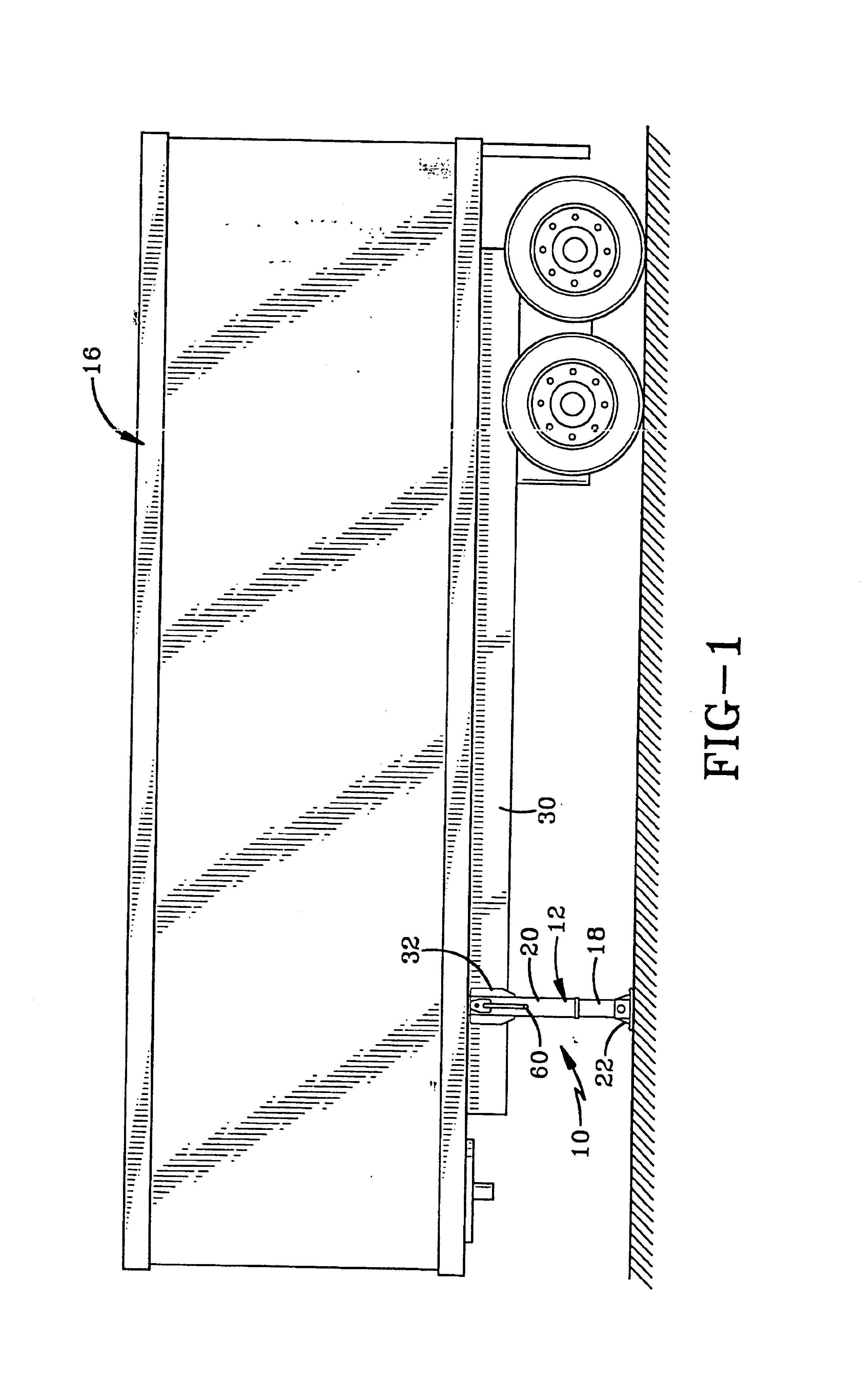
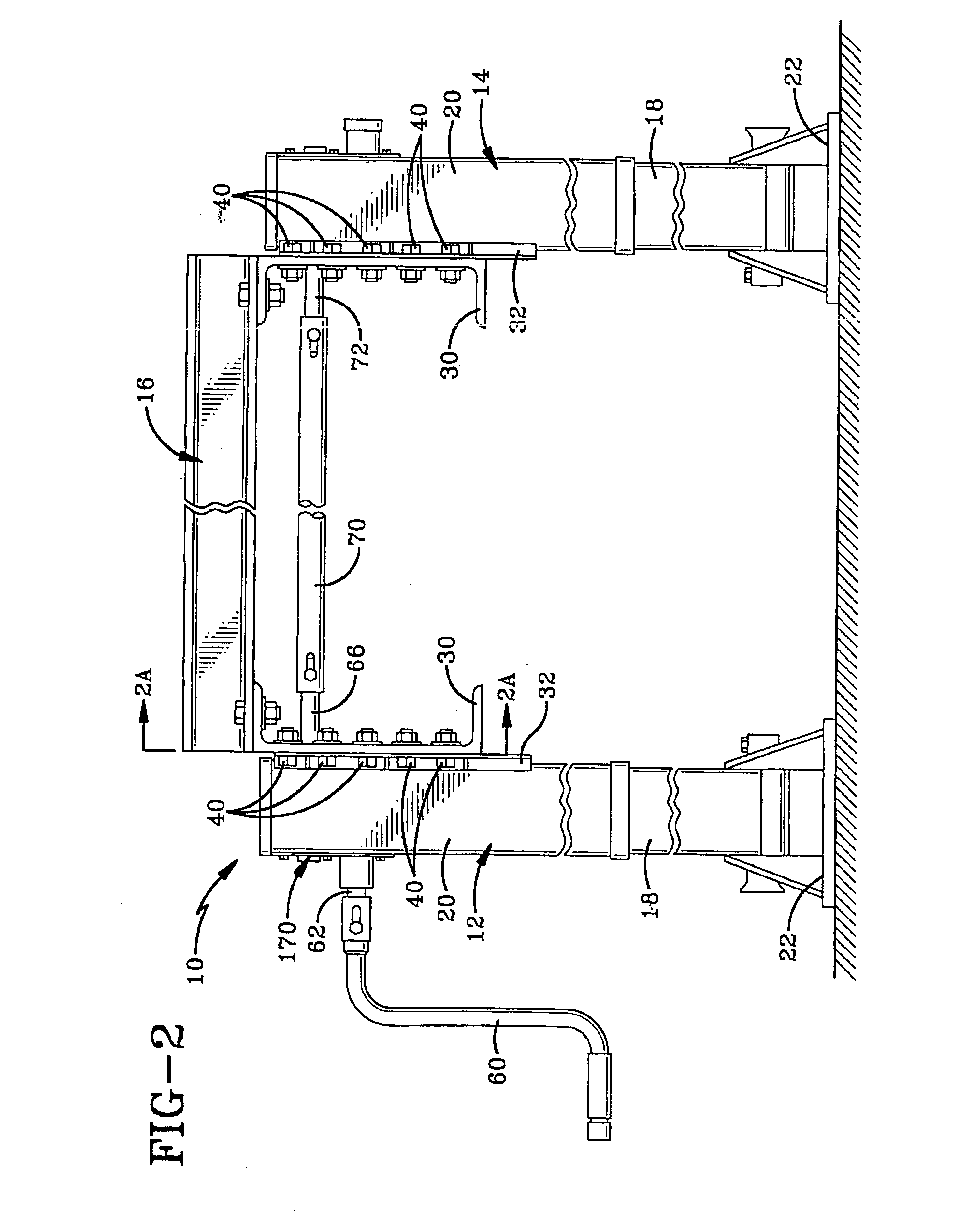
The landing gear of the present invention is indicated generally by the numeral 10 in the accompanying drawings. Landing gear 10 generally includes a pair of vertically extendable and retractable supports in the form of upright, spaced, parallel and opposite side legs 12 and 14 that are connected to the front end of a semitrailer 16. In the embodiment shown in the drawings, cranking leg 12 is disposed on the left or driver's side of semitrailer 16. Cranking leg 12 may also be disposed on the right side of semitrailer 16 if desired.

Each leg 12 and 14 includes a lower tube 18 telescopically disposed within an upper tube 20. A foot 22 is connected to the lower end of each lower tube 18 in a conventional manner.

Semitrailer 16 includes a pair of spaced apart, longitudinally disposed channels 30. Landing gear 10 is mounted to channels 30 in either an inboard configuration as depicted in FIGS. 3 and 8 or an outboard configuration as depicted in FIGS. 1, 2, and 9. In accordance with one of ...


PUM


Abstract

A landing gear assembly for a semitrailer includes a pair of legs that may be simultaneously raised or lowered by turning a single crank. Each of the legs is configured to be able to be mounted in either an inboard or outboard configuration. This is achieved by providing both sides of each leg with no protrusions that extend beyond the space provided in the mounting bracket and the mounting hole used to connect the landing gear to the semitrailer. The gear assembly of the landing gear includes a unique floor base that receives and supports the input shaft. A cover is used to support the input ends of the input shaft and the output shaft. The cover is connected to the input side of the upper tube of the leg and allows the gear assembly to be easily assembled within the perimeter of the upper leg.

Description

BACKGROUND OF THE INVENTION1. Technical FieldThis invention generally relates to semitrailer landing gear and, more particularly, to a landing gear assembly that can be mounted in an inboard or outboard configuration. Specifically, the present invention relates to a single reduction landing gear assembly including a housing having an outer perimeter that fits within the standard mounting bracket for a tractor trailer thus enabling an inboard or outboard mounting configuration. The landing gear also has an improved gear assembly.2. Background InformationTractor trailers are a predominant means of transporting goods throughout the world. Trailers are popular because goods do not have to be loaded and reloaded as trailers can deliver directly to the cargo bay of the destination. Trailers also can be detached from a tractor and pulled by another tractor allowing goods to be transported in a trailer without driver downtime. A driver thus can drop off a loaded trailer for unloading and pi...

Claims


Application Information

Patent Timeline
IPC IPC(8): B60S9/00B60S9/08
CPCB60S9/08
Inventor VANDENBERG, ERVINGALLEGO, JOSE MANUEL ALGUERAMULLER, GERALDPFISTER, STEFFEN
Owner JOST WERKE
Why Eureka
Try Eureka