Projector

a projector and projection device technology, applied in the field of projectors, can solve the problems of inability to show the correct position, difficulty in manual correction of diagonal distortion, and inability to accurately project the image, and achieve the effect of simple structur

Inactive Publication Date: 2005-01-25
SHARP NEC DISPLAY SOLUTIONS LTD
View PDF16 Cites 89 Cited by
  • Summary
  • Abstract
  • Description
  • Claims
  • Application Information

AI Technical Summary

Benefits of technology

The object of the present invention is to provide a projector, which performs a correction of a diagonal direction for a distortion of a projected and displayed image on a screen by a simple structure.

Problems solved by technology

If the correction is only for vertical or horizontal keystone, it can be easily performed manually, but the manual correction is difficult for the diagonal distortion.
However, the above-described prior art comprises a range finder independently from the primary function of the projector, and does not take steps and the like to use a projection image.
With respect to the projection image, since it widely changes the position and size of its image plane depending on a status of the projection lens, it is unknown whether or not a correction adequate to the projected image is really made by simply just measuring the positional relationship between the projector and the screen.
Furthermore, with respect to a position to be measured as well, due to an installation error of the finder and a variation of a mechanical positional relationship between the projection lens and a display device, it is not possible to show a correct position.
In addition, in the case where a frame and the like exist just outside the screen and protrudes endways or the screen itself is set far back and the like, a measured position of the finder and a screen position do not always match.

Method used


Image

  • Projector
  • Projector
  • Projector

Examples


first embodiment

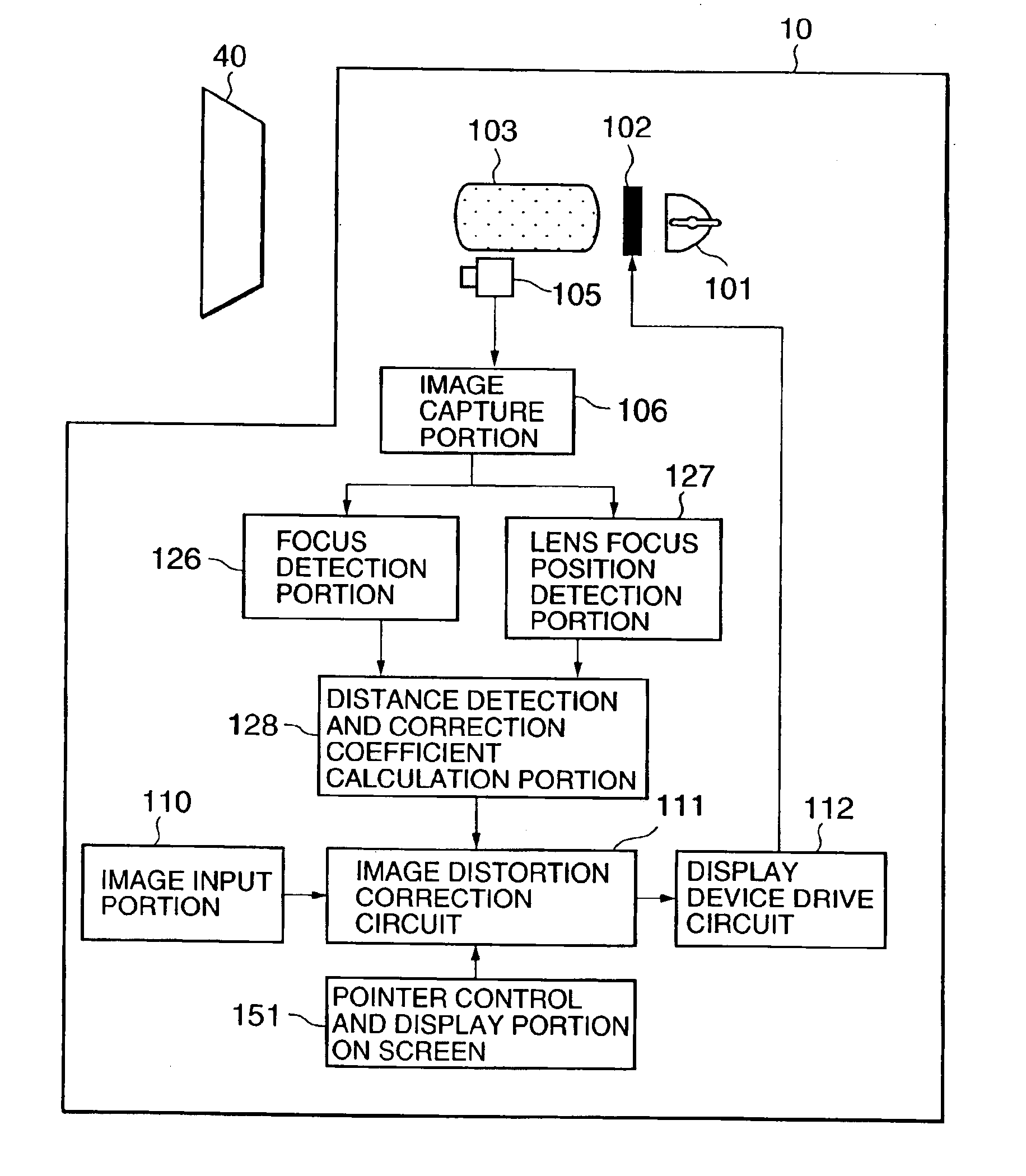
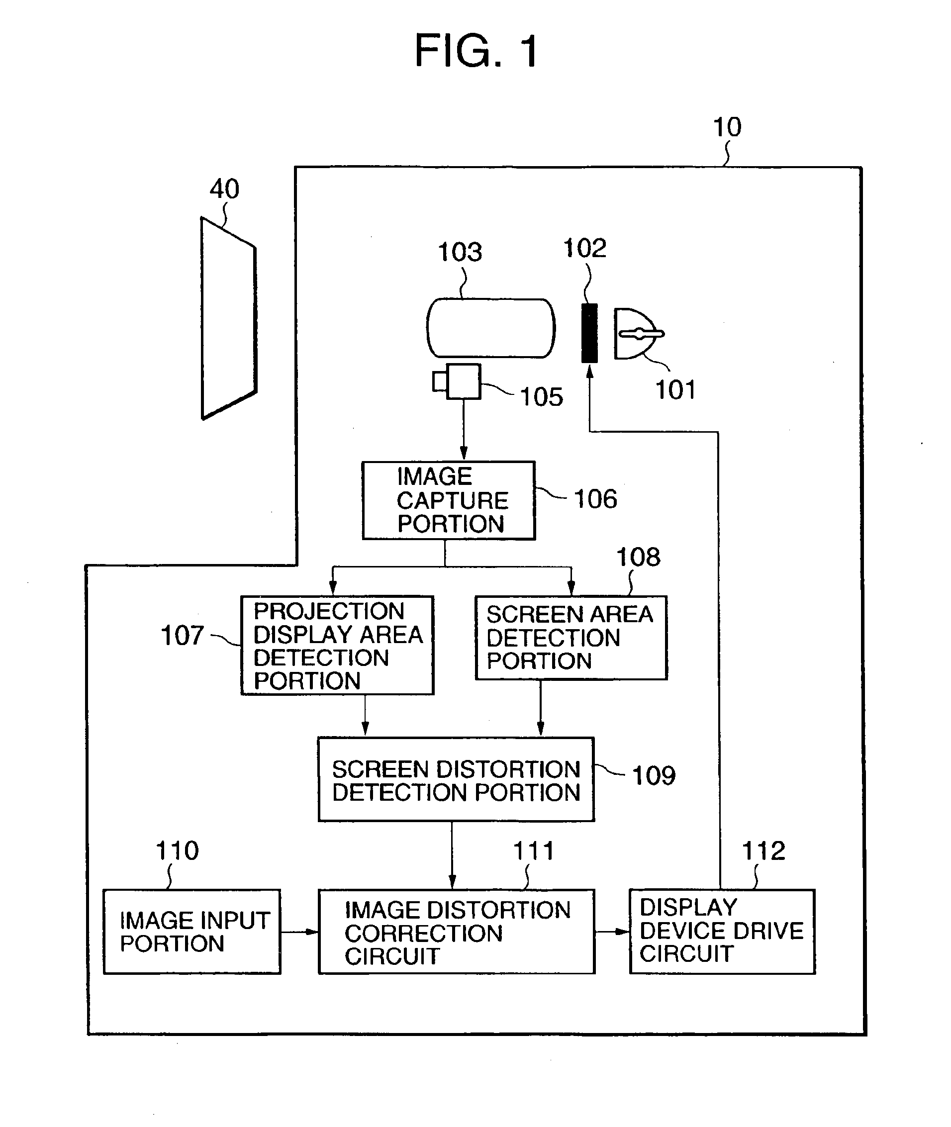
A first embodiment of the present invention will be described. FIG. 1 is a block diagram showing the first embodiment. A projector 10 projects an image and displays it on a screen 40. The projector 10 includes a light source 101, a display device 102, a projection lens 103, an image sensor 105, an image capture portion 106, a projection display area detection portion 107, a screen area detection portion 108, a screen distortion detection portion 109, an image input portion 110, an image distortion correction circuit 111, and a display device drive circuit 112.

A projection image is displayed on the screen 40 through the light source 101, the display device 102 and the projection lens 103. A lamp is used as the light source 101. A liquid crystal panel is used as the display device 102. The image sensor 105 is adjacent to the projection lens 103 and is located at a place as close as it can be ignored in contrast to a distance to the screen 40. The image sensor 105 captures the projecte...

second embodiment

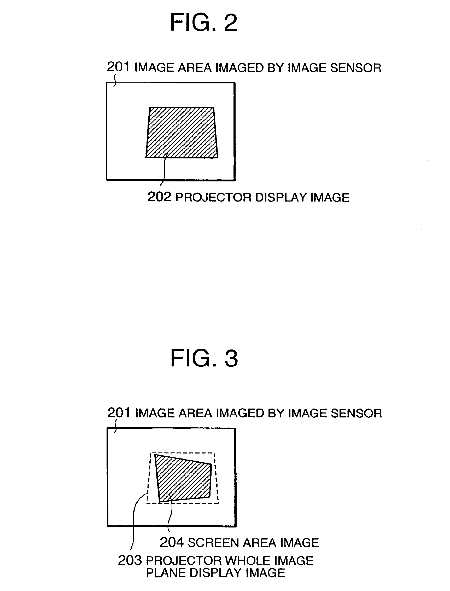
Next, a second embodiment of the present invention will be described. The second embodiment is an embodiment in which a screen area image 204 is not put in place within the area of a projector whole image plane display image 203 when the screen area is detected as shown in FIG. 8.

In this case, the procedure of the first embodiment does not allow the user to obtain a satisfactory image. A coping method in this case will be explained with reference to FIG. 8. A screen area detection portion 108 detects the area of a screen 40 by the same method as that of the first embodiment. A screen distortion detection portion 109 analogously enlarges or shrinks the area and, further, performs a positional movement if necessary. The size and the position of an image, which satisfies the requirements that the image projected to the screen 40 keeps a rectangle and is within the area of the projector whole image plane display image 203, are calculated. By displaying an image on the position of the di...

third embodiment

Next, a third embodiment of the present invention will be described. FIG. 9 is a block diagram showing an optical system of the third embodiment. A projector 10 has a half mirror 113 between a display device 102 and a projection lens 103. The half mirror 113 guides an image passing through the projection lens 103 to an image sensor 105. If the half mirror 113 is of a mobile system, in which the mirror is put between the display device 102 and the projection lens 103 at the imaging time only by an image sensor 105, the half mirror 113 at the time of normal use will not affect the projector 10.


PUM


Abstract

An image sensor is installed in the vicinity of a projection lens. The image sensor images a projected and displayed image and a screen. A projection display area and a screen area are detected from the image imaged by the image sensor. An inputted image data is corrected so that the projection display area matches the screen area. The image to be displayed is automatically displayed in a shape, which matches a display surface of the screen.

Description

BACKGROUND OF THE INVENTION1. Field of the InventionThe present invention relates to a projector which projects and displays an image on a screen.2. Description of the Related Prior ArtHeretofore, it has been a common practice to correct a keystone caused by a tilt projection of an image only by a vertical processing, and the projector used to be installed at a position squarely facing with a screen as far as a horizontal direction is concerned.In recent years, however, with the advent of a correction function for the horizontal keystone, it became possible to perform the corrections vertically, horizontally and diagonally.Among those corrections, the correction for the screen still depends on a manual correction. If the correction is only for vertical or horizontal keystone, it can be easily performed manually, but the manual correction is difficult for the diagonal distortion.There are systems proposed (for example, the inventions disclosed in Japanese Unexamined Patent Applicatio...

Claims


Application Information

Patent Timeline
Patent Type & Authority Patents(United States)
IPC IPC(8): H04N5/74H04N9/31H04N17/00
CPCH04N5/74H04N9/3197H04N9/3194H04N9/3185
Inventor MOCHIZUKI, KAZUOAOYANAGI, HISAKAZUMORIWAKI, DAISUKE
Owner SHARP NEC DISPLAY SOLUTIONS LTD
Why Eureka
Try Eureka