

Turbine generator starting method and turbine generation system
a turbine generator and starting method technology, applied in the direction of electric generator control, turbine/propulsion engine ignition, instruments, etc., can solve the problem of limited utilization of inverters
- Summary
- Abstract
- Description
- Claims
- Application Information
AI Technical Summary
Benefits of technology
Problems solved by technology
Method used
Image

Examples
first embodiment
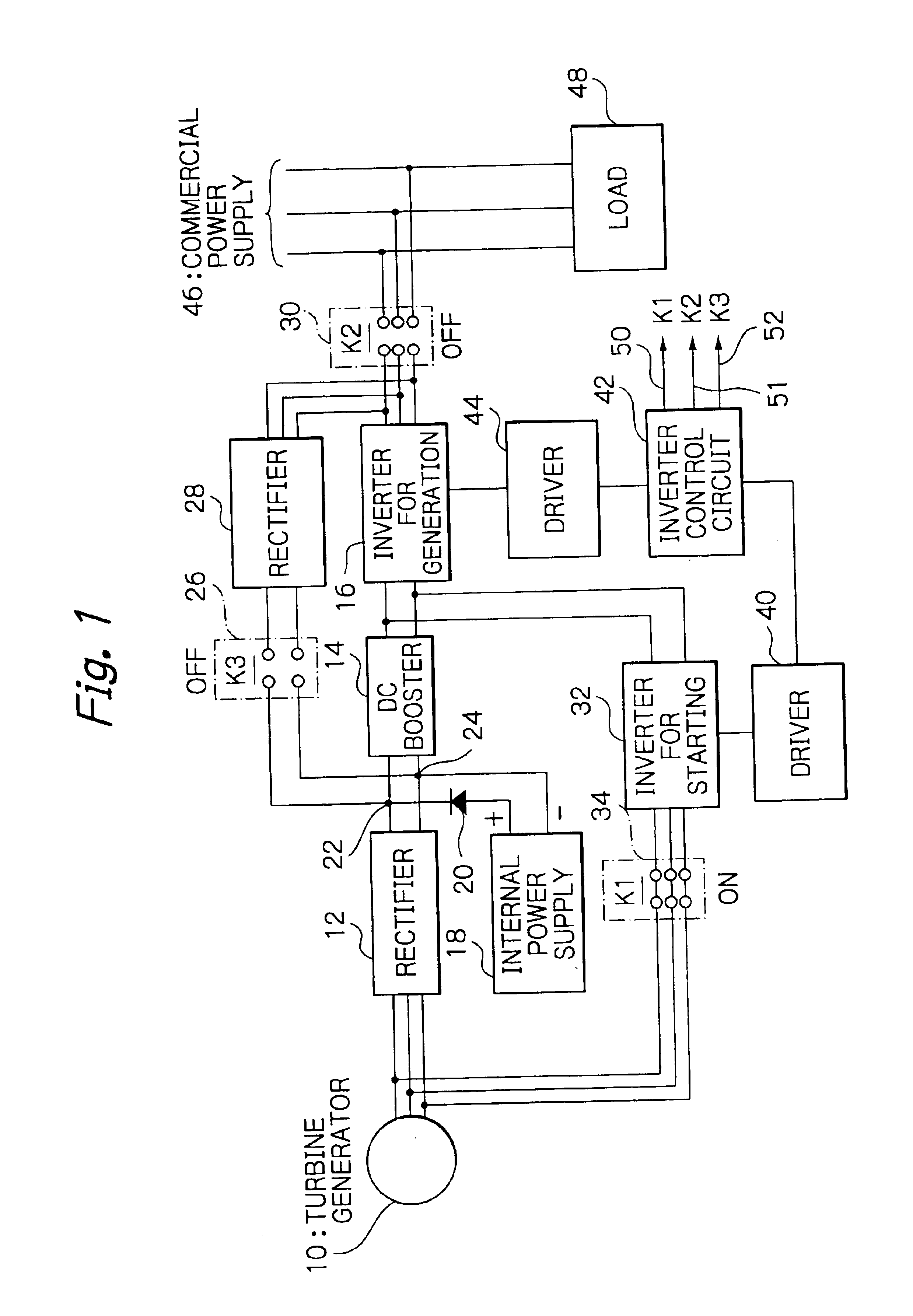
FIG. 1 is a schematic block diagram of a turbine generation system illustrating the present invention. The turbine generation system comprises a turbine generator 10 which is composed of a turbo generator or gas turbine; a rectifier 12 for generation connected to the turbine generator 10; a DC booster 14 as a DC matching circuit connected to the output of the generation rectifier 12; a pulse-width-modulation inverter for generation (main inverter) 16 connected to the output of the DC booster 14; an internal power supply 18 such as a battery and / or a DC storage cell connected to DC buses routed between the generation rectifier 12 and DC booster 14; a pulse-width-modulation inverter 32 for starting connected to the output of the DC booster 14; a driver 40 for driving the starting inverter 32; a driver 44 for driving the generation inverter 16; a first switching means (K1) 34 for activating / deactivating the starting and generation inverters 32 and 16 through the drivers 40 and 44 and f...
second embodiment
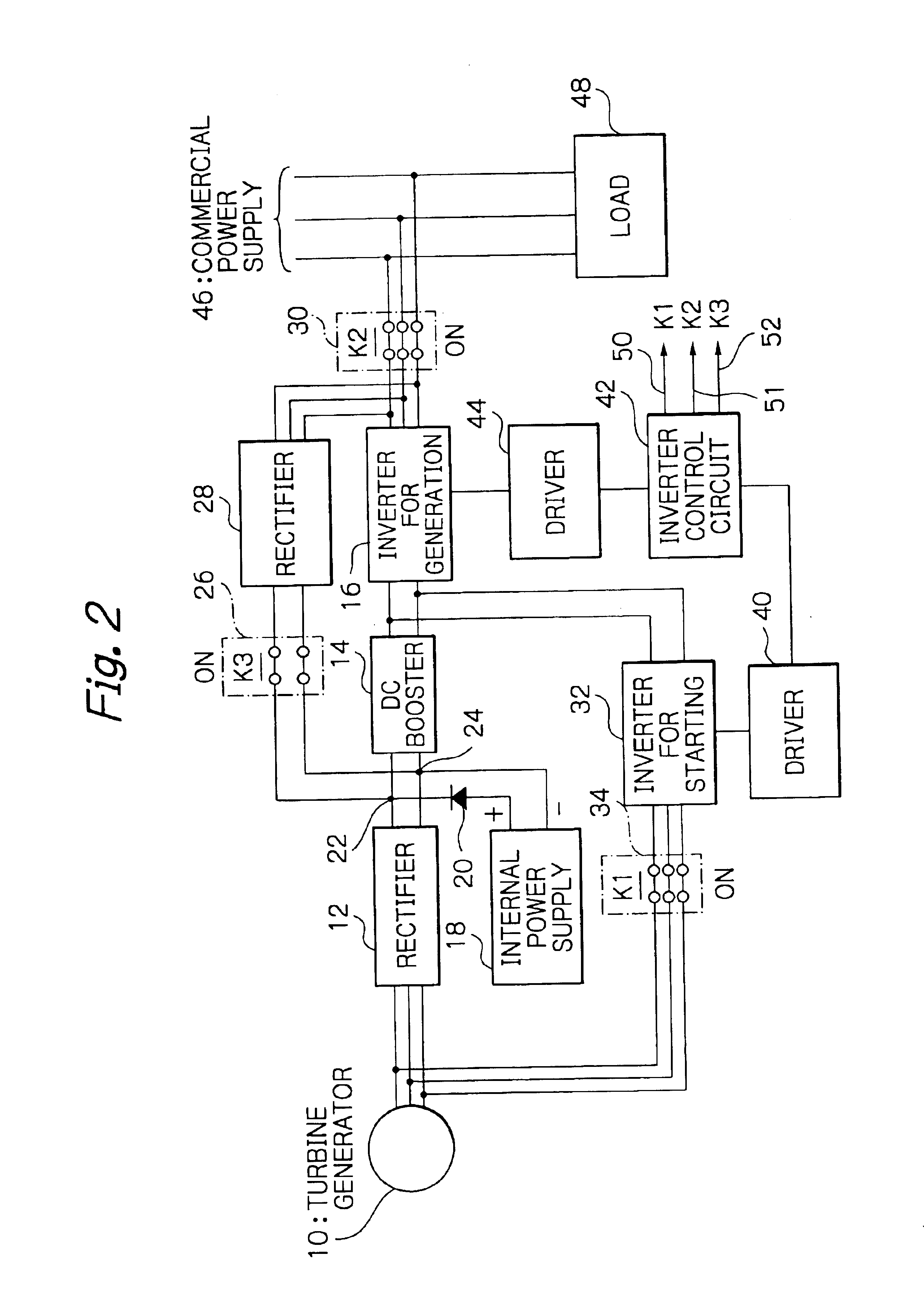
FIG. 2 is a schematic block diagram of a turbine generation system illustrating the present invention. Equivalent members to the generation rectifier 12, DC booster 14, generation inverter 16, internal power supply 18, starting rectifier 28, starting inverter 32, driver 40, driver 44, and inverter control circuit 42 in the foregoing embodiment can be used in the second embodied turbine generation system, so that repeated description thereon is omitted.
The inverter control circuit 42 disables the driver 44 to deactivate the pulse-width-modulation generation inverter 16 (OFF state) connected to the turbine generator 10.
The inverter control circuit 42 also transmits an active K2 control signal 51 to the second switching means 30 to render the second switching means 30 closed. Through the second switching means 30, the commercial power supply 46 of 100 / 200 volts at 50 / 60 Hz, for example, is connected to the starting rectifier 28. The inverter control circuit 42 transmits an active K3 co...
third embodiment
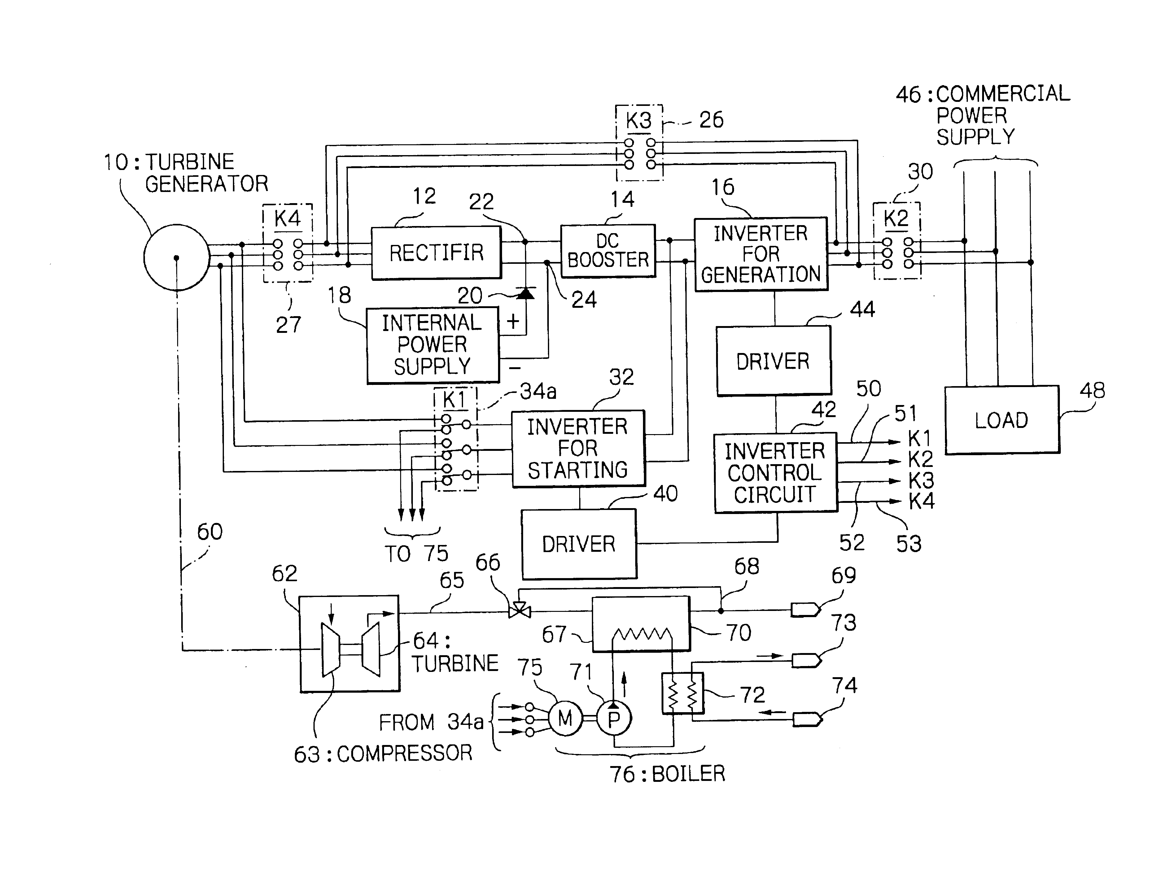
FIG. 4 is a schematic block diagram of a turbine generation system illustrating the present invention. The turbine generation system comprises a turbine generator 10; a rectifier 12 for use in both starting and power generation operation; a DC booster 14 connected to the output of the rectifier 12; a pulse-width-modulation generation inverter 16 connected to the output of the DC booster 14; an internal power supply 18 connected to DC buses 22, 24 routed between the generation rectifier 12 and DC booster; pulse-width-modulation starting inverter 32 connected to the output of the DC booster 14; a driver 40 for driving the starting inverter 32; a driver 44 for driving the generation inverter 16; and an inverter control circuit 42 for controlling, i.e., opening and closing a first switching means (K1) 34a for activating or deactivating the starting and generation inverters through the driver 40 and driver 44 and for connecting / disconnecting the starting inverter 32 to / from the turbine g...
PUM
 Abstract
Description
Claims
Application Information