Flat display unit and method fabricating same

a technology of display unit and flat display, which is applied in the direction of identification means, instruments, optics, etc., can solve the problems of low production efficiency, high production cost, complicated and troublesome handling of protectors, etc., and achieve low cost and high efficiency.

Inactive Publication Date: 2005-01-25
HITACHI CONSUMER ELECTRONICS CORP +1
View PDF5 Cites 81 Cited by
  • Summary
  • Abstract
  • Description
  • Claims
  • Application Information

AI Technical Summary

Benefits of technology

It is another object of the present invention to provide a flat display unit and a method for fabricating the same, wherein the display unit is made possible to protect the display panel thereof by itself, without a prot

Problems solved by technology

To avoid this problem, the conventional flat display unit having a display panel 53 is equipped with a protector 56 as explained with reference to FIGS. 10A and 10B, but it takes time and labor in the attachment and detachment of the protector, and further, in case of large-scale flat display unit comprising a display panel having a screen size as large as the type

Method used


Image

  • Flat display unit and method fabricating same
  • Flat display unit and method fabricating same
  • Flat display unit and method fabricating same

Examples


second embodiment

FIG. 4 is a sectional view showing a plasma display unit according to the present invention.

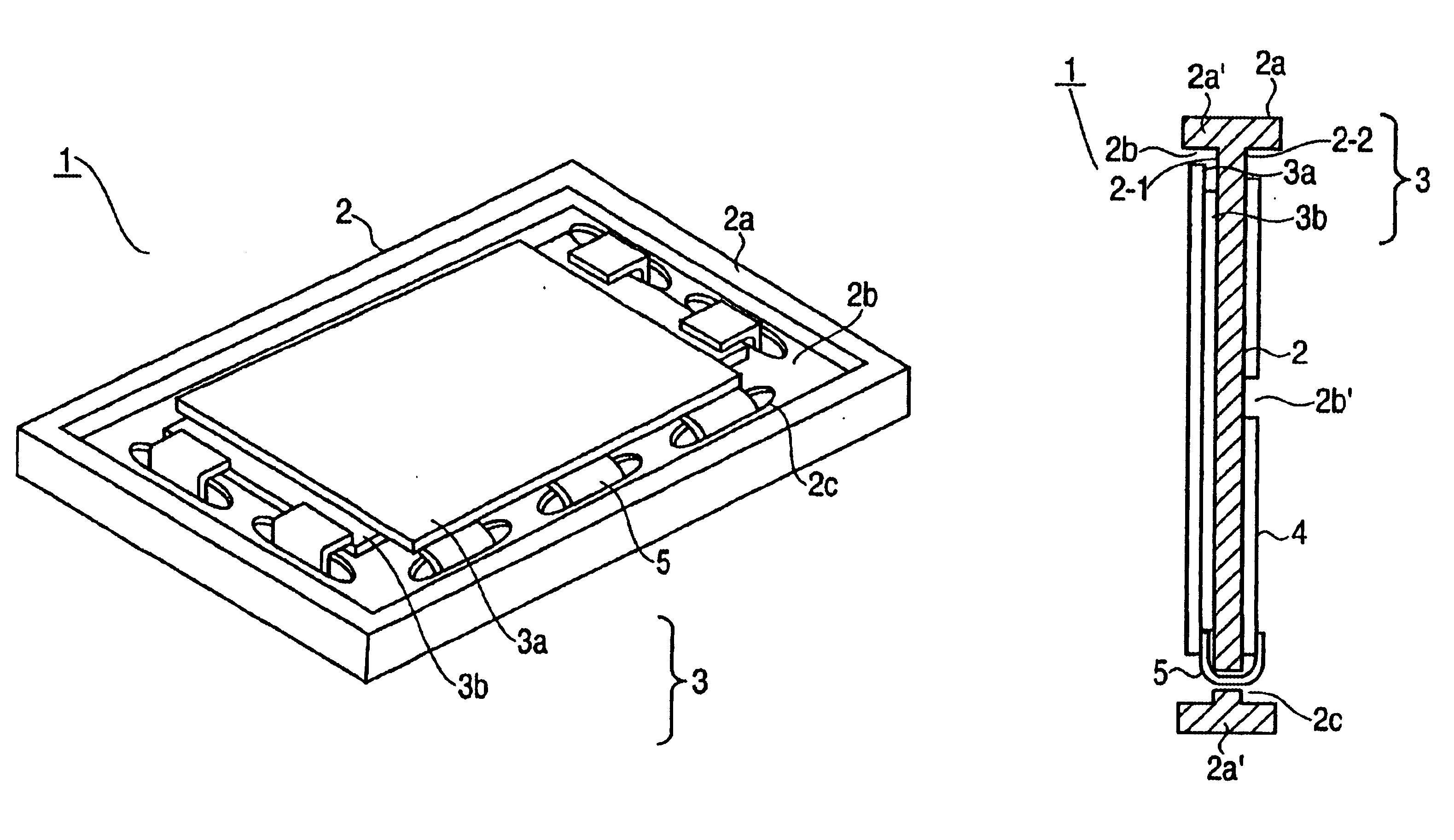
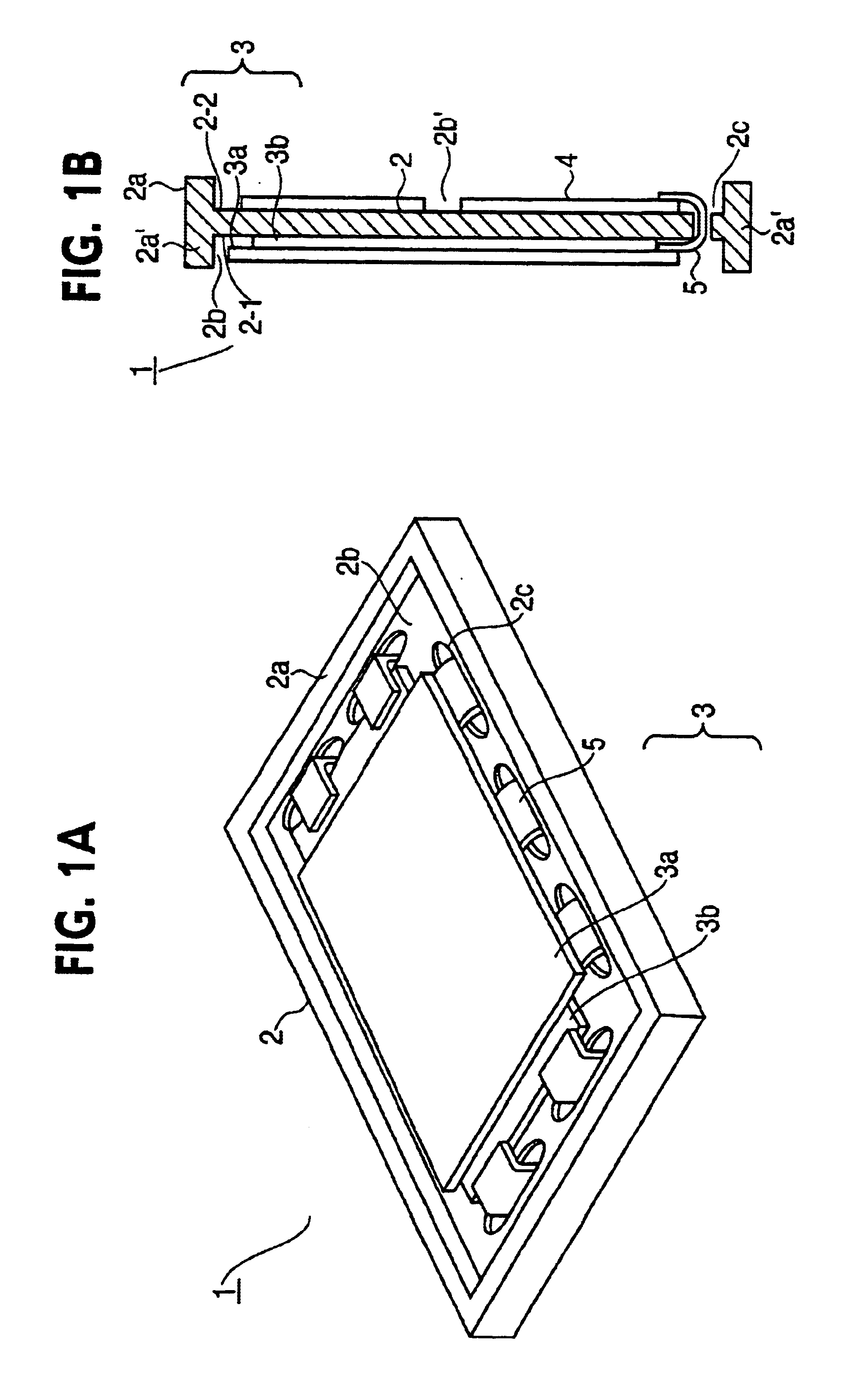
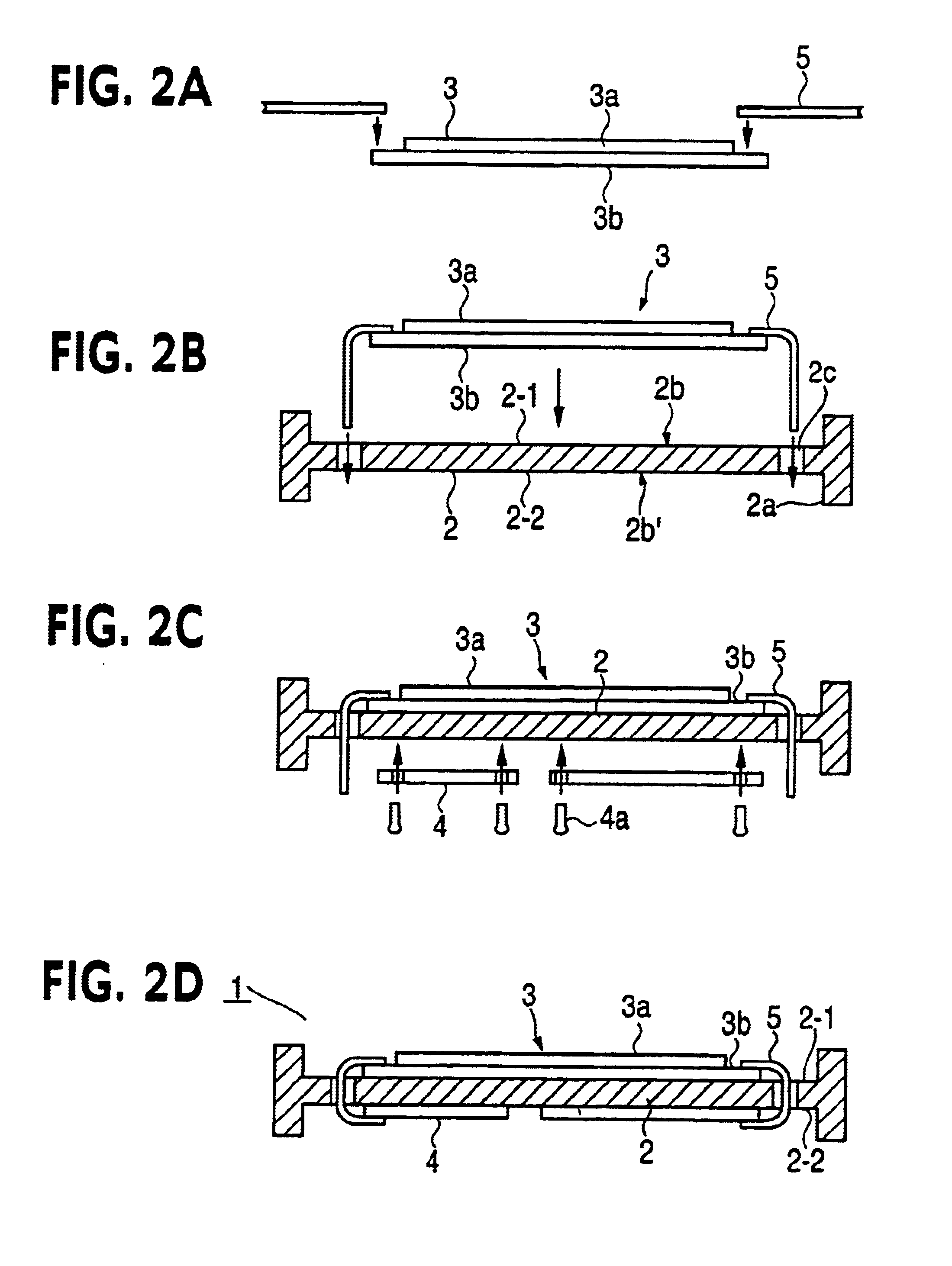
Similarly to the first embodiment, the plasma display unit 21 in this embodiment comprises a chassis 22 having a bank 22a, in which a display panel 23 is adhered to one of a pair of opposite surfaces of chassis 22, and circuit boards 24 are mounted on another of the pair of opposite surfaces of chassis 22.

The difference from the first embodiment is seen in the structure of chassis 22. That is, bank 22a, recesses 22b and 22b′, and through-hole 22c are similarly provided, however, a plurality of protrusions 22d are differently provided for the respective recesses 22b and 22b′ in the pair of opposite surfaces of chassis 2, for improving the heat dissipation characteristics. The plurality of protrusions 22d increases the surface area of chassis 2 and also create spaces 26 between display panel 23 and chassis 22, and, between circuit boards 24 and chassis 22, thus enabling efficient discharge of t...


PUM


Abstract

A flat display unit has a chassis combining a display panel and circuit boards for driving the display panel into a unit in which the display panel and the circuit boards are mounted on respective opposite surfaces of the chassis. The chassis is provided with a bank (i.e., sidewall) extending about the periphery of opposite main surfaces of the chassis including at least the surface on which the display panel is mounted, perpendicularly to that surface and surrounding the periphery of the display panel 3, and hence protecting the display panel without requiring a protector, as is conventionally used during the processes of assembling, testing and transporting thereof. The chassis is also provided with through-holes and optionally with a cut-out, which are formed in the periphery of the chassis, for facilitating interconnections between the display panel and the circuit boards by flexible cables which pass therethrough.

Description

BACKGROUND OF THE INVENTION1. Field of the InventionThe present invention relates to a flat display unit and a method for fabricating the same.Display devices such as plasma display, liquid crystal display, EL (electroluminescence) display and FED (field emission display) are being paid attention as the devices for wall type display apparatus, as is well known.However, these devices usually have a structure composed of one or a pair of glass substrates adhered to each other and, therefore, are mechanically weak, and an improvement to reinforce the mechanical strength of the devices is needed.2. Description of the Prior ArtPrior art flat display unit will be explained with reference to FIGS. 9A, 9B, 10A and 10B by taking a plasma display unit as a typical example, in which FIGS. 9A and 9B are a perspective view and a sectional view thereof, respectively, and FIGS. 10A and 10B are a perspective view and a sectional view, respectively, both showing a protector attached to the display u...

Claims


Application Information

Patent Timeline
IPC IPC(8): G02F1/13G09F9/00G02F1/1333
CPCG02F1/13452G02F1/133308G02F2001/133325G02F2001/133322G02F2001/133317G02F1/133317G02F1/133322G02F1/133325G09F9/00
Inventor YOSHIMURA, HIROSHIIWAI, MORIMITSUKAWAHARA, KOUICHI
Owner HITACHI CONSUMER ELECTRONICS CORP
Why Eureka
Try Eureka