Fabrication rules based automated design and manufacturing system and method

a technology of automatic design and manufacturing system, applied in the direction of stacking articles, instruments, de-stacking articles, etc., can solve the problems of time-consuming and laborious, time-consuming, and labor-intensive, and achieve the effect of reducing labor intensity, reducing labor intensity, and reducing labor intensity

Inactive Publication Date: 2005-01-25
VLT
View PDF56 Cites 86 Cited by
  • Summary
  • Abstract
  • Description
  • Claims
  • Application Information

AI Technical Summary

Benefits of technology

Implementations of the invention may include one or more of the following features. Laser ablation may be used to remove the insulation. A bonding agent may be applied to the cable in an area around the preselected area for mechanically securing the tap to the cable. An insulating layer may be applied to cover the preselected area. The cable may be folded along an axis aligned with the length of the cable. The cable may be bent along an axis perpendicular to the length of the cable. A discontinuity may be formed in a preselected one of the plurality of conductors. The cable may include a plurality of control conductors and at least two power distribution conductors. The electrical connection may be formed by soldering.
In another general aspect of the invention, a electrical apparatus includes two or more component modules, each occupying a respective volume having respective overall height, width, and length dimensions, and at least two electrical connection terminals. A planar interconnection structure has a first and a second conductive layer separated by insulation. The planar structure is adapted for making connection to the electrical connection terminals of each component module and for lying in a space along an edge of the respective volume within the overall height dimension and without being located adjacent to more than three sides of each module. The planar structure provides electrical connections between the electrical connection terminals.
Implementations of the invention may include one or more of the following features. The planar interconnect structure may include circuit board material having a conductive layer which is cut and routed in the fashion of a point-to-point wire cable. The modules may have an indentation and the planar structure may have a width adapted to fit within the indentation. The electrical connection terminal may include a pin having a portion generally perpendicular to the board at a connection point. A hole for accepting the pin and a conductive eyelet in the hole and electrically connected to the first conductive layer may be provided for making electrical connection to the pin. An insulative sleeve may be used to provide insulation between the eyelet and the second conductive layer. The first and second conductive layers may comprise power conductors. A third conductive layer is separated from the first conductive layer by insulation and includes at least two signal lines formed by removing conductive material from the third conductive layer. Jumper landings make electrical connection between a selected one of the connection terminals and a selected one of the signal lines.
A cable having a plurality of signal conductors may also be provided. The cable may be held in a position substantially perpendicular to the board. A connection bracket includes a contact for engaging a selected one of the connection terminals, a flat cable supporting surface for maintaining the cable in position, and a selective cable connection portion for selectively connecting to a selected one of the plurality of conductors. At least one of the signal lines may include a discontinuity between modules.
In another general aspect of the invention, a method of interconnecting components includes providing a flat multilayer laminate having a plurality of conductive layers separated by insulation. A section of the laminate is cut to have a predetermined shape. Portions of an exposed one of the conductive layers is removed by machining to from a plurality of conductive traces. A hole is machined in the laminate to form a connection to a preselected one of the conductive layers. The hole has a first width in the preselected layer and a second larger width in the other conductive layers. A conductive eyelet is inserted into the hole for making contact with the preselected one of the conductive layers.
Implementations of the invention may include one or more of the following features. An insulative sleeve is provided in the hole for insulating the eyelet from at least one of the other conductive layers. At least two jumper landings are formed and a jumper is soldered to form a connection between the landings or a conductive layer is pad printed to form a connection between the jumper landings. An insulative layer may be pad printed over the laminate in an area between the jumper landings before the conductive layer is pad printed. A discontinuity may be formed in a preselected one of the plurality of conductors. The laminate may include a top conductive layer for forming signal lines and at least two interior conductive layers for distributing power. One end of the eyelet may be clinched after it is positioned in the hole.

Problems solved by technology

Design of a custom power supply involves different skills and usually takes months to complete.
In addition, money and effort must also usually be invested in the development and qualification of manufacturing processes and equipment for each different custom power supply.
However, weeks or months of effort are still often required to perform the packaging, thermal and other design and qualification tasks required to develop a custom power supply using power components.

Method used


Image

  • Fabrication rules based automated design and manufacturing system and method
  • Fabrication rules based automated design and manufacturing system and method
  • Fabrication rules based automated design and manufacturing system and method

Examples


Embodiment Construction

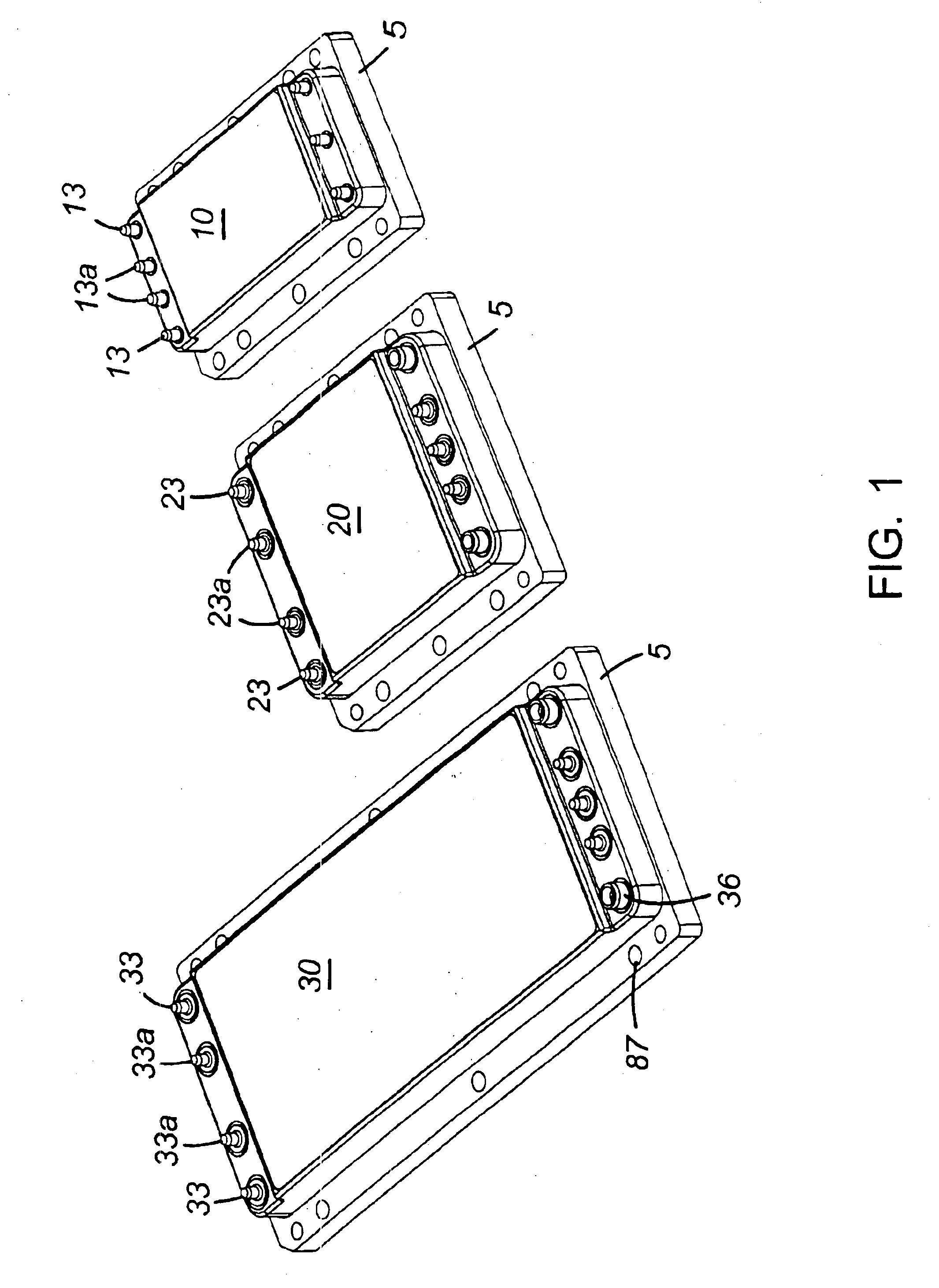
Referring to FIG. 1, high density, modular DC-DC converters are available in a wide variety of input voltage, output voltage and power levels. For example, three different styles of power converter modules micro 10, mini 20, and maxi 30 (corresponding, for example, to the 700, 800, and 900 Series of DC-DC converters manufactured by Vicor Corporation, Andover, Mass., USA) are shown in FIG. 1. For a given combination of input and output voltage ratings (e.g., 48 V nominal input, 5 V output; or 300 V nominal input, 48 V output), the maximum amount of power which can be delivered by a power converter module in a particular package is related to the package size. A converter module in package style 10 might be rated to deliver up to 150 Watts of output power at a baseplate 5 temperature rating of 100 degrees Celsius for example. Similarly, converter modules in package styles 20 and 30 might be respectively rated to deliver up to 250 and 600 Watts of output power at the same 100 degrees C...


PUM


Abstract

An automated custom power supply design system uses an expert system containing a set of rules, including manufacturing limitations to limit design choices and ensure feasibility and manufacturability of the design. A design interface collects specifications from a user. A complement of power components for satisfying the electrical specifications is defined and mechanical specifications for each component are provided by the system for use in creating the mechanical design. After the mechanical design is established a thermal analysis is performed and the completed design is returned to a host computer. After an order is received, a computer integrated manufacturing system generates all of the specifications required to manufacture the components for the system and the system.

Description

BACKGROUND OF THE INVENTIONThis invention relates to automatically designing custom power converters.Power converters accept power from an electrical input source and convert it into a form suitable for use by electrical loads. One class of power conversion systems, called power supplies, are typically used to convert power derived from a utility source, such as an AC utility line or a DC telecommunications battery, into one or more regulated DC voltages (e.g., 5V, 12V, 48V) used for powering electronic circuitry. Specifications for a power supply are application specific. Thus, while many power supplies may share certain common characteristics such as a similar input voltage range or the presence of a 5-volt output, many power supplies are customized, by design, for use in a particular product or system.Design of a custom power supply involves different skills and usually takes months to complete. For example, a typical custom power supply design may involve design of electronic po...

Claims


Application Information

Patent Timeline
Patent Type & Authority Patents(United States)
IPC IPC(8): G06F17/50B65G61/00
CPCG06F17/50G06F2217/78G06F2217/36G06F30/00G06F2113/16G06F2119/06
Inventor VINCIARELLI, PATRIZIOFOLEY, JEREMIAH NOELNOWAK, SCOTT WILLIAMSKOOLICAS, CHARLES STEVEN
Owner VLT
Why Eureka
Try Eureka