Method for determining juxtaposition of physical components with use of RFID tags

a technology of physical components and juxtaposition, applied in the field of radio frequency identification systems, can solve the problems of inability to fix problems or provide new services, large amount of cost, incomplete, incorrect or ambiguous knowledge of a network,

Inactive Publication Date: 2005-01-25
ALCATEL-LUCENT USA INC +1
View PDF11 Cites 295 Cited by
  • Summary
  • Abstract
  • Description
  • Claims
  • Application Information

AI Technical Summary

Benefits of technology

The present inventor has recognized that Radio Frequency Identification (RFID) tags can be advantageously used to provide a framework for automatically determining the connectivity of or the proper alignment (e.g., abutment) between physical components, including, for example, network cables and devices, as well as components assembled by automated manufacturing systems. As is well known to those skilled in the art, RFD technology allows an object bearing an RFID tag to be located in physical space—for example, it is well known that it can easily be determined that an object bearing an RFID tag is at least “near” an RFID sensing device. This is clearly quite useful in a number of common prior art applications of this technology, such as inventory management in retail and wholesale applications, automatic toll collection, tracking of vehicles, etc. Recently, however, the accuracy with which the location of an RFID tag (and thus the object bearing the RFID tag) can be located in three-dimensional space has improved significantly, which advantageously enables an additional and valuable class of new applications.

Problems solved by technology

The management of complicated networks such as telecommunications networks or sophisticated computer networks is tremendously expensive.
A substantial portion of this cost arises from incomplete, incorrect or ambiguous knowledge about a network.
For example, a telecommunications network operator may not have an accurate record of how network switches are configured, leading to failed attempts to fix problems or provision new services.
However, a more fundamental ambiguity arises at the physical level of network cable management.
However, it is very difficult to maintain an accurate record of exactly which cable is connected to what device port of what piece of equipment, since the cables may so easily be connected, disconnected, and reconnected.
In a large telecommunications or computer network system, it is an extremely expensive proposition to keep track of every cable, where it is, where it runs, and what device port on which piece of equipment it is plugged into.
As a result, equipment inventory databases are notoriously inaccurate, and the negative results include, inter alia, loss of network capacity, increased service times and a much greater chance of disruptive service errors.
Another problem, seemingly unrelated to the network cable connectivity problem discussed above, involves automated manufacturing systems.
Unfortunately however, vision systems are extremely expensive and work only very locally within a limited field of view.

Method used


Image

  • Method for determining juxtaposition of physical components with use of RFID tags
  • Method for determining juxtaposition of physical components with use of RFID tags
  • Method for determining juxtaposition of physical components with use of RFID tags

Examples


Embodiment Construction

A First Illustrative Embodiment of the Present Invention

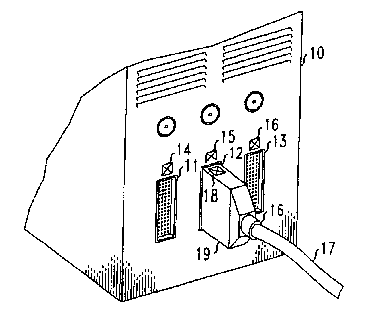
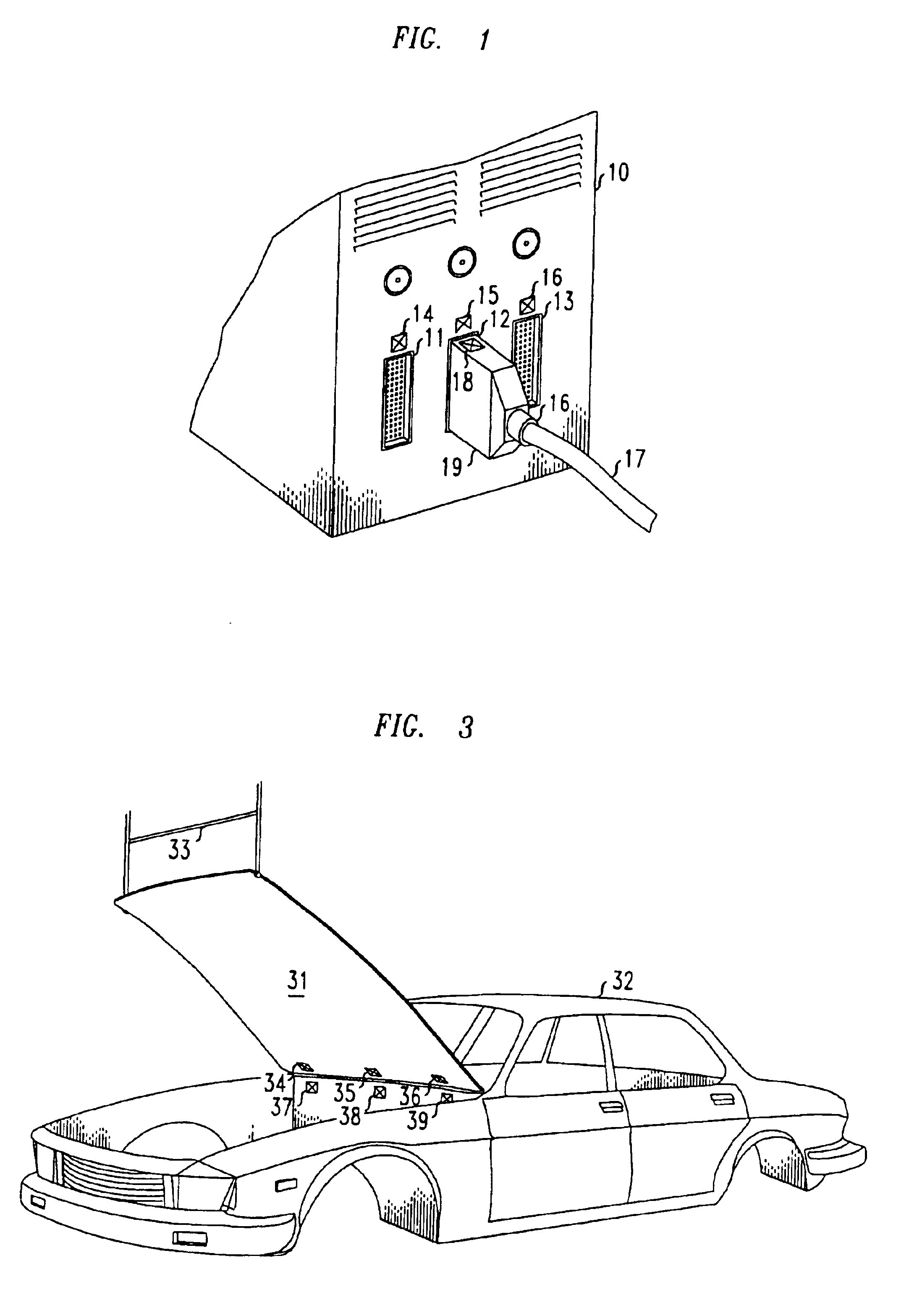
FIG. 1 shows an illustrative cable and a piece of equipment, each with RFID tags attached thereto in accordance with a first illustrative embodiment of the present invention. The illustrated piece of equipment, device 10, has three device ports—device port 11, device port 12 and device port 13—each with a corresponding RFID tag—namely, tag 14, tag 15 and tag 16, respectively—attached to the faceplate of device 10 in very close proximity to the corresponding device ports. In addition, cable 17 has RFID tag 18 attached to cable connector 19 thereof. It will be obvious to those skilled in the RFID art that a number of high precision RFID sensors, which are not explicitly shown in the figure, will necessarily be located in the general vicinity of the components shown in the figure—such as, for example, on the walls of the room in which the components are located—in order to be able to accurately determine the locations of the vario...


PUM


Abstract

Radio Frequency Identification (RFID) tags are used for automatically determining the connectivity or alignment between physical components, including, for example, connectivity of network cables and device ports, as well as alignment of components assembled by automated manufacturing systems. In one embodiment of the invention, accurate determinations of the physical three-dimensional locations of cables and equipment are employed to determine which cables are plugged into which device ports of which pieces of equipment. In another embodiment of the invention, multiple RFID tags are used to determine the appropriate alignment between components being assembled by an automated manufacturing system.

Description

FIELD OF THE INVENTIONThe present invention relates generally to the field of Radio Frequency Identification (RFID) systems and more particularly to the use of RFID tags for determining the connectivity of or the proper alignment (e.g., abutment) between physical components.BACKGROUND OF THE INVENTIONThe management of complicated networks such as telecommunications networks or sophisticated computer networks is tremendously expensive. A substantial portion of this cost arises from incomplete, incorrect or ambiguous knowledge about a network. For example, a telecommunications network operator may not have an accurate record of how network switches are configured, leading to failed attempts to fix problems or provision new services. This lack of knowledge can in some instances be remedied by polling the networking equipment to determine its actual settings.However, a more fundamental ambiguity arises at the physical level of network cable management. Network cables may be added, remov...

Claims


Application Information

Patent Timeline
Patent Type & Authority Patents(United States)
IPC IPC(8): G06K17/00
CPCG06K17/0029G06K17/00
Inventor BOHANNON, PHILIP L.
Owner ALCATEL-LUCENT USA INC
Why Eureka
Try Eureka