Thread machining control method and apparatus therefor

Active Publication Date: 2005-01-25
OKUMA CORP
View PDF7 Cites 12 Cited by
  • Summary
  • Abstract
  • Description
  • Claims
  • Application Information

AI Technical Summary

Benefits of technology

The present invention has been made in view of the above-described circumstances, and one of the objects thereof resides in providing thread machining control method and apparatus therefor capable of attaining a stable thread machining process even when a speed of a spindle is varied.

Problems solved by technology

However, when a screw cutter of a formed shape, such as a thread machining tool (bit) is used, cutting chatter is liable to occur in general, so that a stable cutting process cannot be carried out.
However, when the rotational number of the spindle is varied in a thread machining process, an acceleration / deceleration error of a slave shaft varies, and a phase error occurs in the relation between the position of the spindle and that of the feed axis, so that a thread machining accuracy markedly decreases.
This causes the accuracy of the thread machining pitch to be deteriorated.

Method used


Image

  • Thread machining control method and apparatus therefor
  • Thread machining control method and apparatus therefor
  • Thread machining control method and apparatus therefor

Examples


Embodiment Construction

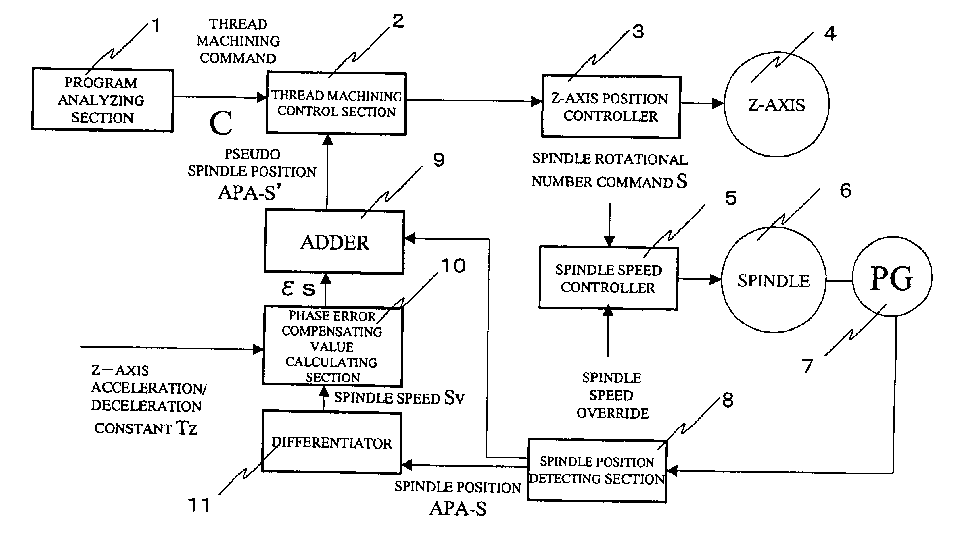
When a spindle is rotated and a phase difference between the phase of a spindle and that of a position of a Z-axis having a predetermined position (marker position) as a starting point is set to zero, a general equation of the phase difference εz occurring when the spindle is moved from the predetermined position to a position in which the Z-axis accelerated reaches a steady speed comes to be the following equation (1).

εz=Sv×P×Tz / 2  (1)wherein “Sv” represents an actual rotational number of the spindle; “P” a screw pitch; and “Tz” a Z-axis acceleration / deceleration constant, the actual rotational number Sv of the spindle being determined on the basis a variation quantity of a spindle position APA-S.

Therefore, in order to stand the Z-axis so that the phase difference between the phase of the position of the spindle and that of the position of the Z-axis having the marker position as a starting point becomes zero, the marker position is compensated and controlled by an angle correspond...


PUM

PropertyMeasurementUnit
Angleaaaaaaaaaa
Speedaaaaaaaaaa
Accelerationaaaaaaaaaa

Abstract

It is strongly demanded that a stable thread machining process be attained by carrying out a thread machining operation while varying the rotational frequency of a spindle, and thereby restraining the occurrence of cutting chatter. According to the present invention, in which a thread machining process is carried out on the basis of a rotation of the spindle and a movement of a feed axis, the above-mentioned demand is met by executing the steps of determining a relative phase error of the spindle positions and feed axis during a thread machining operation, and determining a movement quantity of the feed axis on the basis of a pseudo spindle position set by error-compensating the quantity of the relative phase error with respect to the spindle position.

Description

BACKGROUND OF THE INVENTION1. Field of the InventionThe present invention relates to a thread machining control method for numerically controlled machine tools, and a thread machining apparatus.2. Description of the Related ArtA related art thread machining control method is adapted to rotate a spindle in accordance with a spindle rotational number command S, determines a movement quantity of a feed axis by multiplying a rotational angle of the spindle by a screw pitch command P after the spindle reaches a predetermined position M (generally called a “marker position”), and thereby drives and controls the spindle. In short, the feed axis is controlled as a slave shaft with a speed of the spindle used as a master.The related techniques will now be described with reference to a block diagram of FIG. 1.A spindle 6 is rotated and controlled via a spindle speed controller 5 on the basis of a spindle rotational number command S given by a processing program. A spindle position detecting s...

Claims


Application Information

Patent Timeline
IPC IPC(8): G05B19/18B23Q15/00B23G1/02
CPCG05B19/182Y10T409/300112Y10T409/300168G05B2219/45215
Inventor SUGIE, MASAYUKI
Owner OKUMA CORP
Why Eureka
Try Eureka