Contacted three dimensional sole measurer

a three-dimensional, contacted technology, applied in the direction of instruments, diagnostic recording/measuring, applications, etc., can solve the problems of pain and inconvenience in walking, many people's feet will become distorted, and the worst of such can even become malformed, so as to achieve the effect of higher measuring precision

Inactive Publication Date: 2005-01-25
ULTRAFOOT HONG KONG
View PDF1 Cites 8 Cited by
  • Summary
  • Abstract
  • Description
  • Claims
  • Application Information

AI Technical Summary

Benefits of technology

After data gathering, the acquired data may be changed into numerical quantity, and the discretely analog data from each individual senor recording its individual displacement is converted into three dimensional drawings after data processing by the electrical components of the device or a communicating device adapted to receive the data and render the three dimensional footprint. As such, the disclosed device can recognize the displacement of each of the displacement sensors, interpret that data into three dimensional footprint drawings, and achieve a higher measuring precision and more stable result than conventionally used foot measuring devices.

Problems solved by technology

However, because of physiology causes, many people's feet will become distorted after years of walking.
The worst of such can even become malformed.
Such distortion and malformation can bring about pain and inconvenience in walking and also result in inappropriate standing posture.
However, with weakness of low measuring precision, unstable results, complex structure and requiring facilities for people to lie down so that the measurer can take the data, this device cannot work effectively in obtaining data.

Method used


Image

  • Contacted three dimensional sole measurer
  • Contacted three dimensional sole measurer
  • Contacted three dimensional sole measurer

Examples


Embodiment Construction

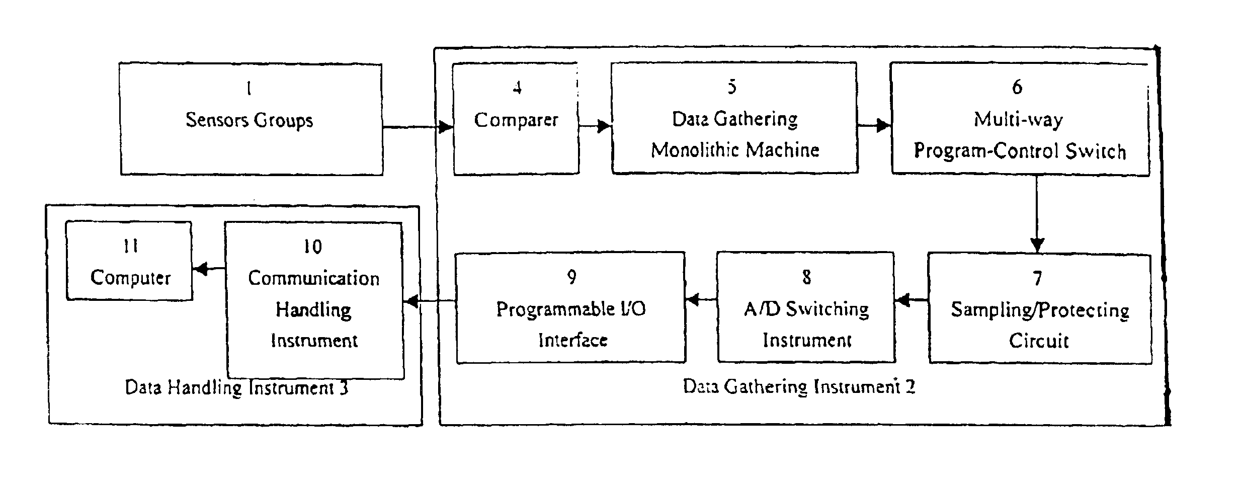
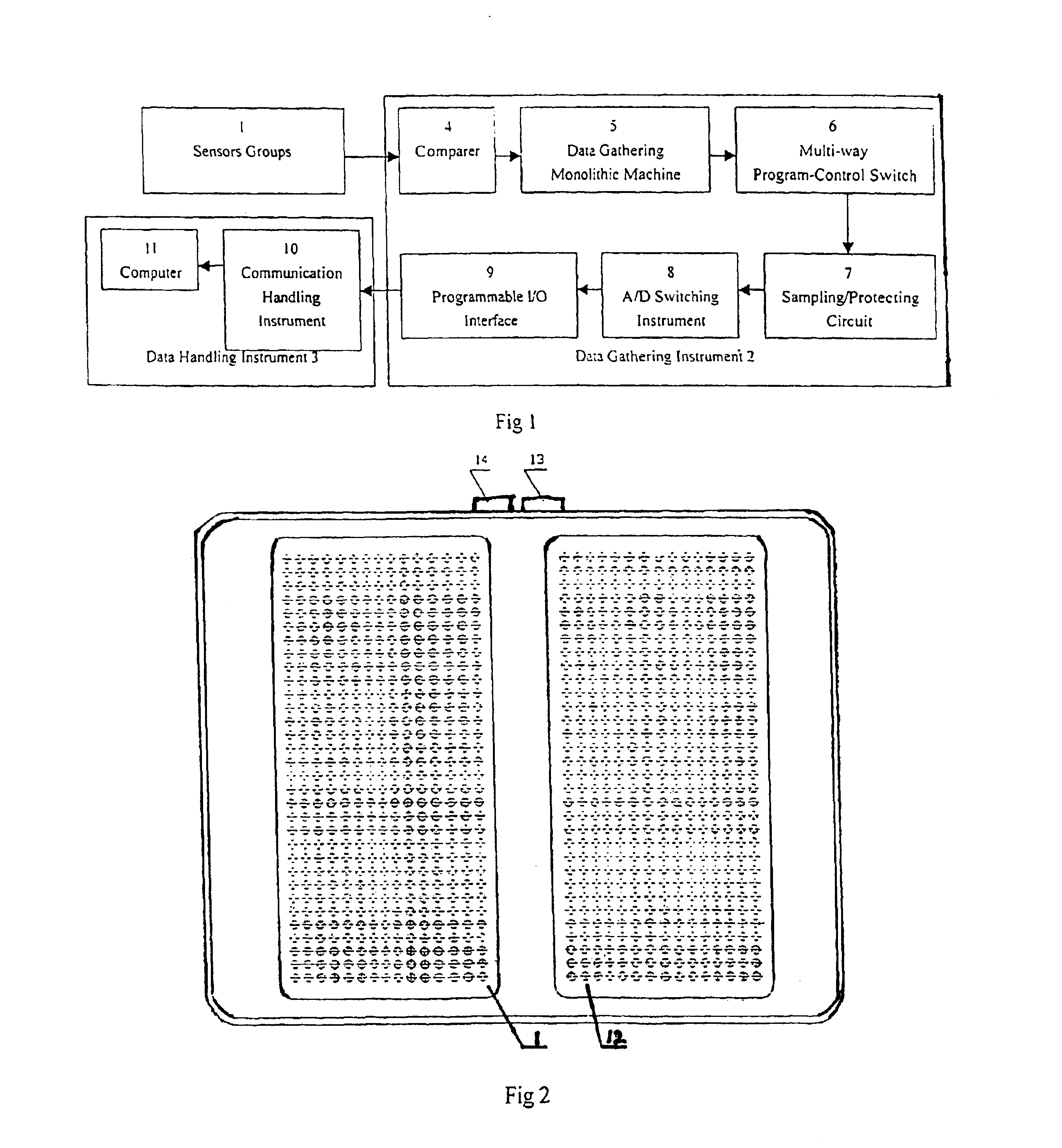
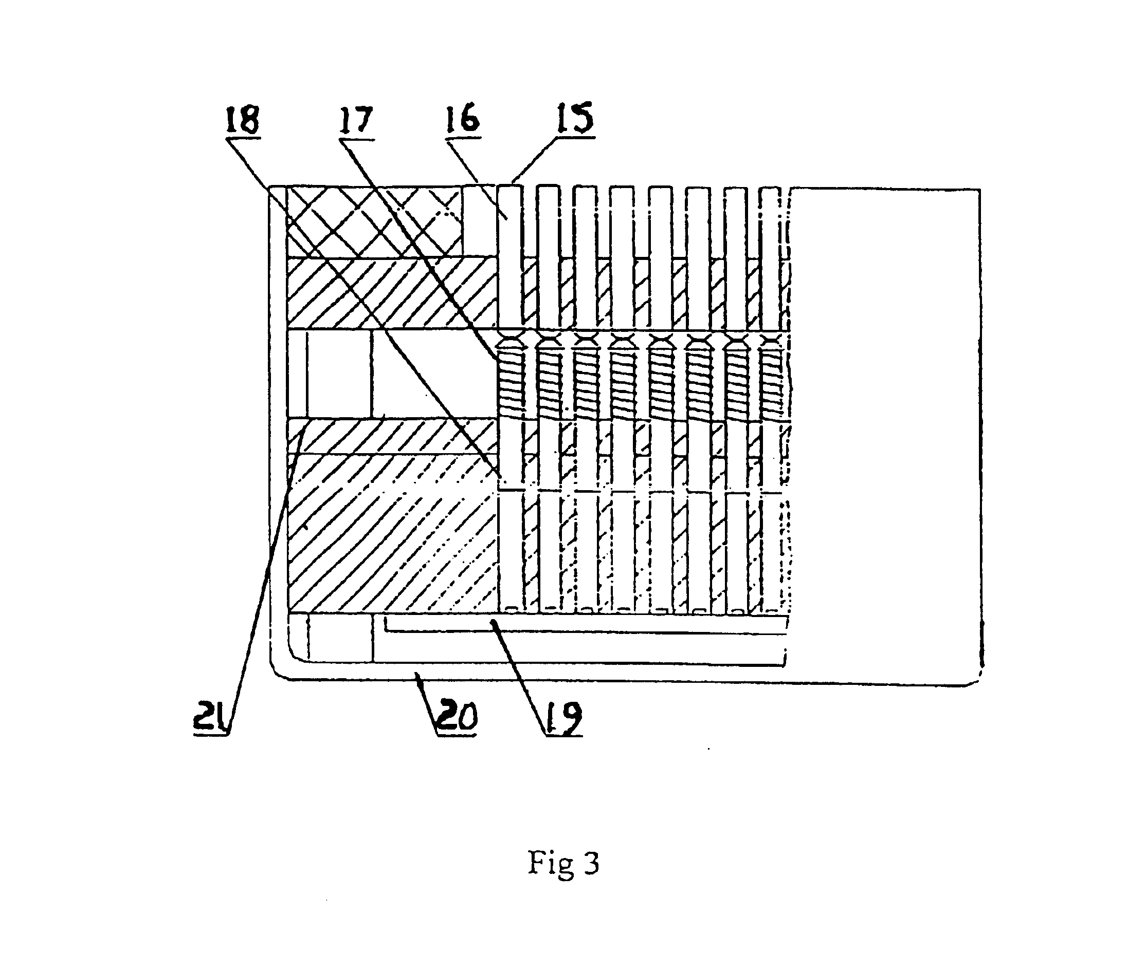
As shown in the accompany drawings 1-3, the disclosed device is composed of a case (20), a power outlet (14) and data interface (13) at a sidewall of the case (20). A number of circuit boards (19) are located inside the case (20) for receiving data from the individual lateral displacement sensors which communicate with the top surface of the case. Three uninstall boards (21) are located in the middle of the case (20). The sensor groups (1) are vertically installed on the uninstall boards (21).

The sensor groups (1) are placed on the case (2) to form at least one and preferably two, rectangle lattices or sensor groups of touch heads (15) arranged upright which communicate with the top surface and communicate their linear displacement with linear displacement sensors (12). The spacing apart of the center axis of the plurality linear displacement sensors (12) making up the sensor groups is currently best at substantially equal to or less than 15 mm. The spacing is equidistantly distribu...


PUM


Abstract

The disclosed device features is a contacting three dimensional sole measuring device to produce accurate three dimensional renditions of the bottom of a human foot placed thereon. The device features one or a plurality of sensors groups communicating with the top surface of a case. Each sensor group is dimensioned to accommodate the area of a footprint of a human foot when placed on top of it. Each sensor group is composed of a plurality of linear displacement sensors which measure the displacement caused by the bottom surface of the foot and communicate that displacement to a data processing device which compiles a three dimensional rendition of the bottom of the foot surface from the individual data points from the displacement senors. Accurate renditions of the bottom surface of a human foot may be achieved by a person simply standing on the sensor groups barefoot.

Description

FIELD OF THE INVENTIONThis application claims the benefit of PRC Application No. 02270909.6 filed Jun. 10, 2002. The disclosed device relates to sole measuring equipment for measuring the soles of the feet. More particularly it relates to a device which when contacting the feet of a human standing upon it will provide a three dimensional (3D) sole measurement.BACKGROUND OF THE INVENTIONThe foot is a very important part of the human body. However, because of physiology causes, many people's feet will become distorted after years of walking. The worst of such can even become malformed. Such distortion and malformation can bring about pain and inconvenience in walking and also result in inappropriate standing posture. The device herein disclosed taking into account the importance of feet in human movement, applies high technology illumination methods to measure human foot shapes by rectifying the biologic power line to plumb centrally. Such precise measurements can assist in the manufa...

Claims


Application Information

Patent Timeline
Patent Type & Authority Patents(United States)
IPC IPC(8): A43D1/00A43D1/02A61B5/107
CPCA43D1/025A61B5/1077A61B5/1074G01B7/28
Inventor LIANG, JIANXIONGLIANG, ZHIQIANGFENG, SHAORONG
Owner ULTRAFOOT HONG KONG
Why Eureka
Try Eureka