Decompression device for power generator engine

a technology for decompression devices and power generators, which is applied in the direction of electronic control, valve details, valve arrangement, etc., can solve the problems of difficult and expensive lever manufacturing, many users are unable to generate the force required to start the engine, and the decompression device is costly and time-consuming to manufactur

Inactive Publication Date: 2005-02-01
YAMAHA MOTOR POWER PROD KK
View PDF13 Cites 15 Cited by
  • Summary
  • Abstract
  • Description
  • Claims
  • Application Information

AI Technical Summary

Problems solved by technology

However, to turn the crankshaft, the piston must be forced against the pressure in the combustion chamber.
Consequently, many users are unable to generate the force required to start the engine.
Some decompression levers include multiple parts or complic...

Method used


Image

  • Decompression device for power generator engine
  • Decompression device for power generator engine
  • Decompression device for power generator engine

Examples


Embodiment Construction

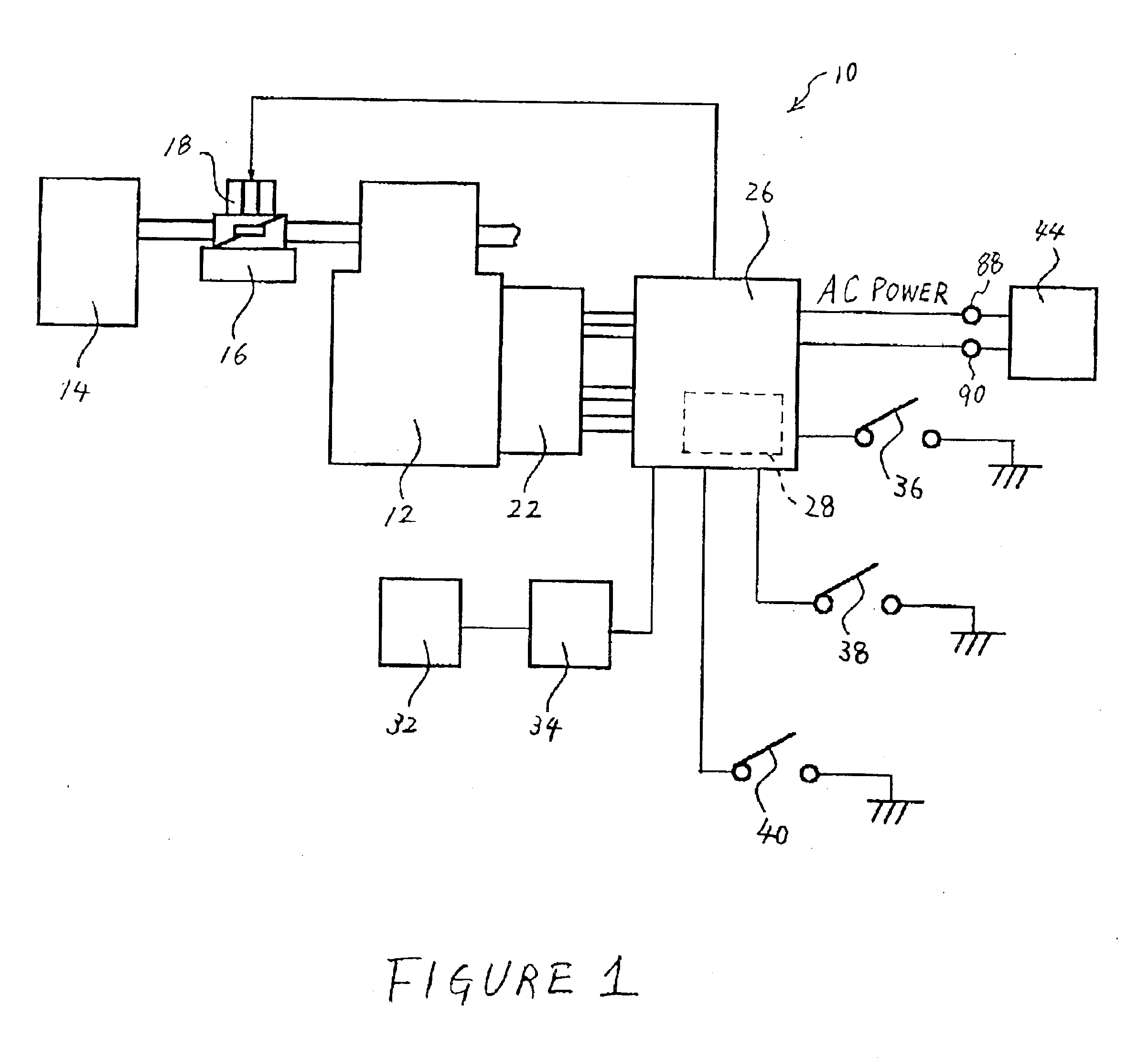
Overall Structure of Engine-Driven Generator

An overall structure of an engine-driven generator 10 that can be used with various features, aspects and advantages of the present invention is illustrated in FIG. 1. The illustrated engine-driven generator 10 generally comprises an internal combustion engine 12. The engine 12 can comprise one or more cylinders that form combustion chambers. The combustion chambers and cylinders may have any orientation (e.g., in-line, V configuration, opposed, vertical or horizontal). The engine 12 can operate in accordance with any combustion principle (e.g., four-cycle, two-cycle, rotary, or the like).

The engine 12 preferably comprises an air intake system, a fuel supply system, an ignition system and an exhaust system. A plenum chamber 14 draws air into the intake system. The plenum chamber 14 advantageously smoothes the air and reduces intake noise. A carburetor 16 is included as a portion of the intake system and as a portion of the fuel supply syst...


PUM


Abstract

A decompression device for an engine reduces pressure in the engine's combustion chamber thereby reducing the amount of force required to start the engine. The decompression device incorporates a decompression lever that cooperates with a cam surface to hold engine valves open longer than normal while the engine is being started. The decompression lever has a weight section and a lifter section. The lifter section is located near a pivot location on the decompression lever and is generally the same thickness as the weight section. The lifter section protrudes beyond the cam gear to hold the engine valves open longer while starting the engine. After the engine has started, the decompression lever rotates into a retracted position to allow the engine valves to open and close normally.

Description

BACKGROUND OF THE INVENTION1. Field of the InventionThe present invention relates to a decompression device for an engine that changes the opening and closing movement of engine valves to decrease the pressure in a combustion chamber while starting the engine.2. Description of the Related ArtConventionally, a small four-cycle engine for use in a generator or another device has one or more cylinders. A piston is located inside a cylinder, and the piston and the cylinder define a combustion chamber. The engine also includes an intake port to supply air and fuel to the combustion chamber and an exhaust port to allow exhaust gases to exist the combustion chamber. The intake port and exhaust port are opened and closed by an intake valve and an exhaust valve, respectively. When the air and fuel mixture is ignited in the combustion chamber, the piston is driven toward a crankcase chamber of the engine. The reciprocal movement of the piston rotates the crankshaft. A cam gear, which is drive...

Claims


Application Information

Patent Timeline
IPC IPC(8): F02D29/06F02D15/04F02B63/04F01L13/08F02D15/00F02B63/00F02D13/04F02D13/02
CPCF01L13/085F02B63/04F02D13/04F02D15/04F02D29/06F02D13/0276F01L2201/00F01L2800/00F02D2013/0292
Inventor KOBAYASHI, MISATOMAKINO, SATOSHI
Owner YAMAHA MOTOR POWER PROD KK
Why Eureka
Try Eureka