Non-contact electric power supply system for a rail-guided vehicle

a technology of electric power supply system and rail guide, which is applied in the direction of power rails, ways, cable arrangements between relatively moving parts, etc., can solve the problems of reducing the efficiency of electric feed cables. , to achieve the effect of eliminating the output reduction, and reducing the output reduction

Inactive Publication Date: 2005-02-01
TOYOTA IND CORP
View PDF5 Cites 15 Cited by
  • Summary
  • Abstract
  • Description
  • Claims
  • Application Information

AI Technical Summary

Benefits of technology

A purpose of the present invention is to eliminate the transition lines between the above-described fixed rails and movable rails and to provide a non-contact electric power supply system in which feed line impedance is stabilized.
To this end, the present invention is divided into a first high-frequency supply source for use with the fixed rails and a second high-frequency supply source for use with the movable rails. Because the system is configured to fix in place the transition lines connecting the complementary fixed sections of rails that are disconnected at the rails' movable sections, the present invention reduces the output reduction due to abrupt inductance changes.
In addition to the fixed transition lines, the power lines extending from the second high-frequency supply source to a movable rail, also, are fixed in place, using a detached-type transformer. As a result, the present invention eliminates the output reduction resulting from abrupt changes in inductance.
Further, by having the power lines extending from the commercial supply source to the second high-frequency supply source utilize a detached-type transformer, and by fixing the second high-frequency supply source on the lateral table, the feeder lines are immobilized, thus eliminating the output reduction caused by abrupt changes in inductance. Installation is also simplified, because the gap in the detached-type transformer may be easily enlarged.
By winding the electric feed lines for the movable rails in multiple turns around a detached-type transformer, thinner lines can be used, thereby simplifying winding around and installation to the transformer cores.

Problems solved by technology

To facilitate rail movement, however, it is necessary to provide the transition lines joining electric feed cables with some degree of slackness.
Where rails are affixed to a ceiling, the slack regions of the transition lines inevitably hang down, thus interfering with work and rail traffic below.
This effectively dilutes the purpose of fixing the rails to a ceiling and undermines the utilization efficiency at locations where rails are so fixed, as well as the efficiency of work crews performing tasks beneath those locations.
A high-frequency supply source is unable to follow the pace of the inductance change in the electric feed cables, even where a source-side feedback control endeavors to compensate for the change in output.
Consequently, power output fluctuates, and an unstable power supply is likely, particularly in the case of output reduction.
In consequence thereof, the circumvention of the electric feed cables becomes difficult.
If the floor is of metal construction, moreover, the likelihood of a further increase in inductance and attendant output reduction increases, given the resultant conductive heating and excessive current.

Method used


Image

  • Non-contact electric power supply system for a rail-guided vehicle
  • Non-contact electric power supply system for a rail-guided vehicle
  • Non-contact electric power supply system for a rail-guided vehicle

Examples


Embodiment Construction

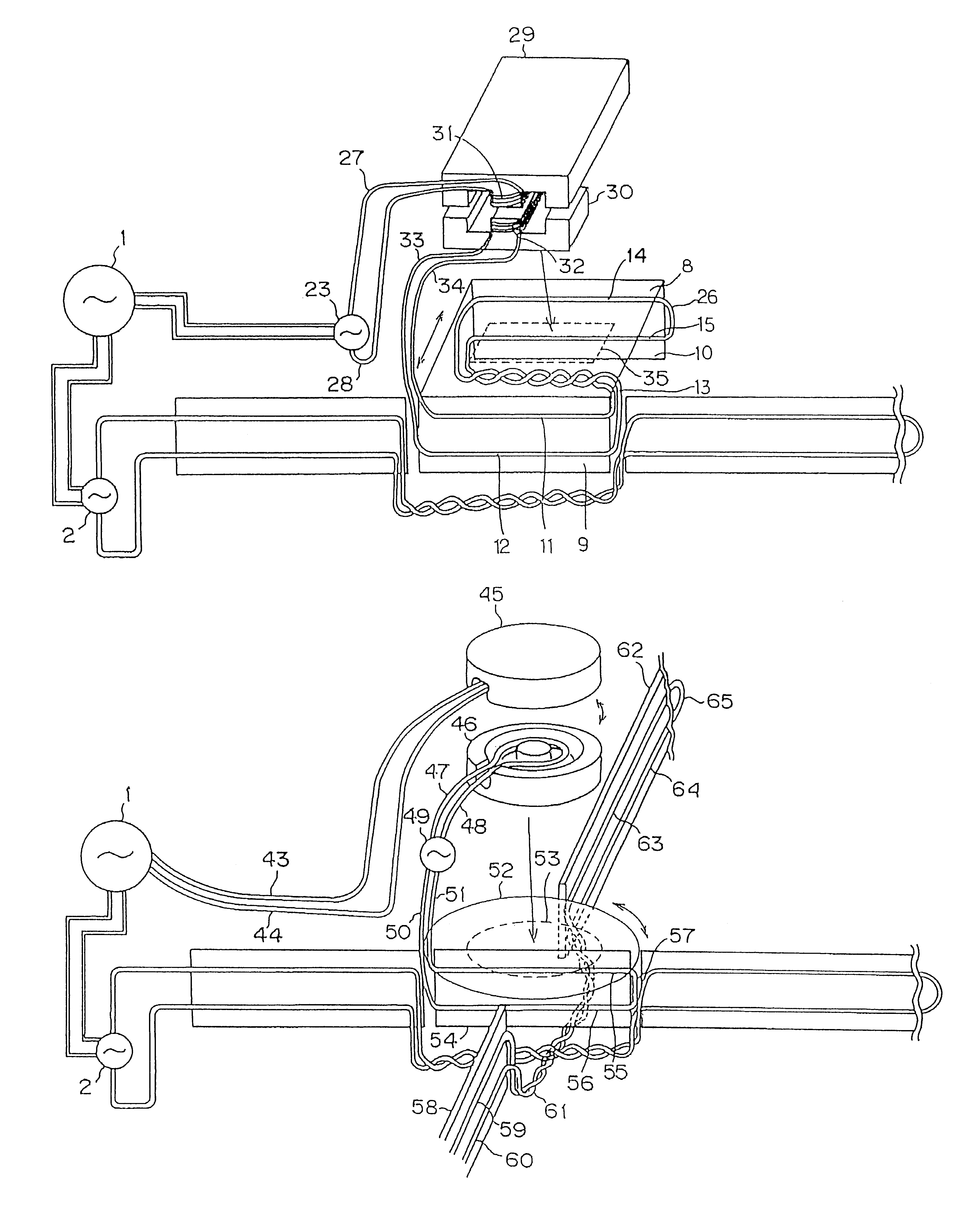
The preferred embodiment of the present invention is hereunder explained in detail, using the accompanying drawings.

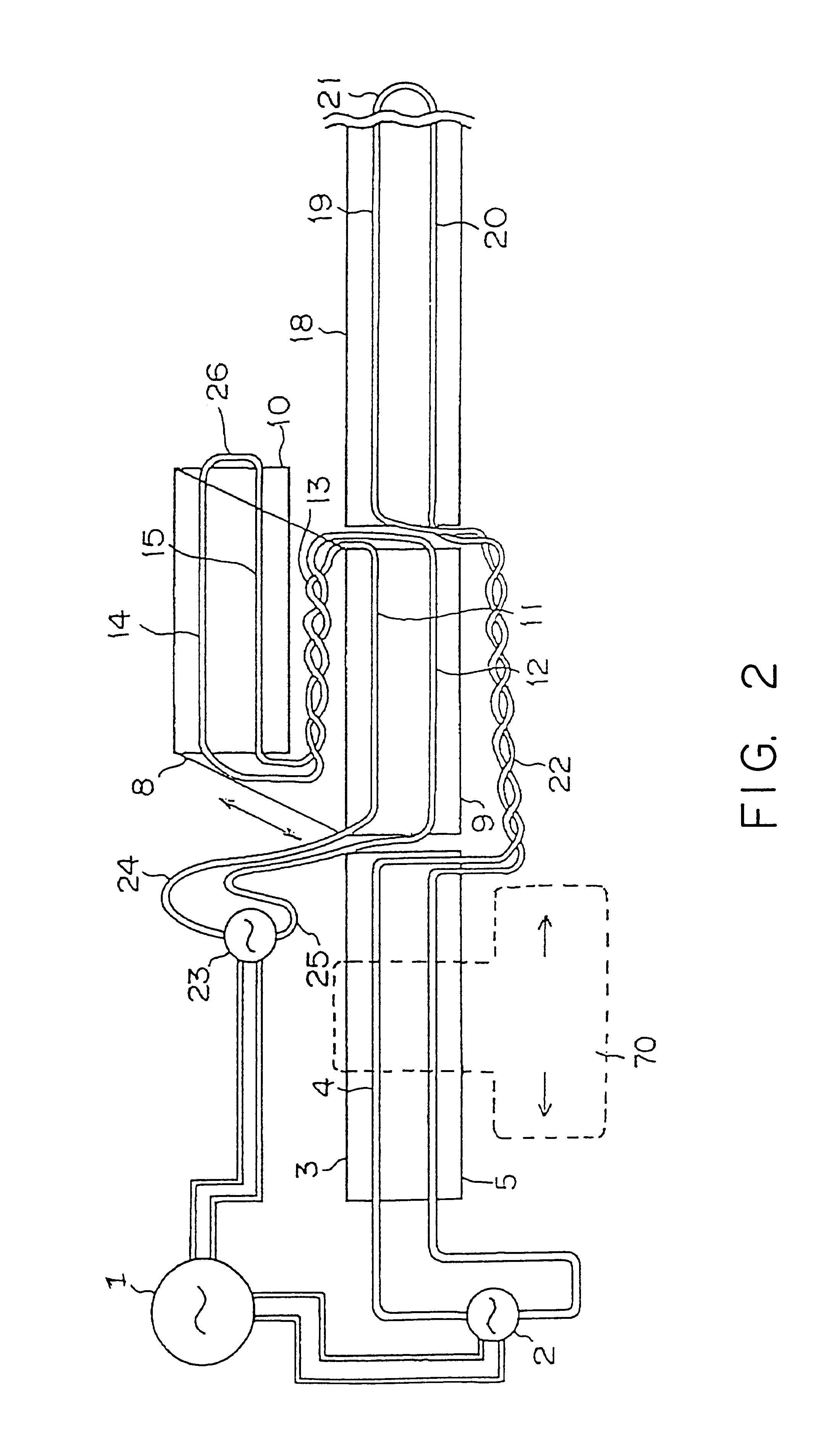
FIG. 2 discloses the overall configuration of the preferred embodiment of the present invention in a terminal platform for connecting established cables.

Items in FIG. 2 that appear in FIG. 1, also bear the same numbers assigned thereto. Any overlapping description is therefore omitted from the following explanation regarding FIG. 2.

Similarly, items in FIG. 3 to FIG. 5 possessed of common numbers refer to the same components and sections. Any references to overlapping descriptions are, therefore, omitted from the specification.

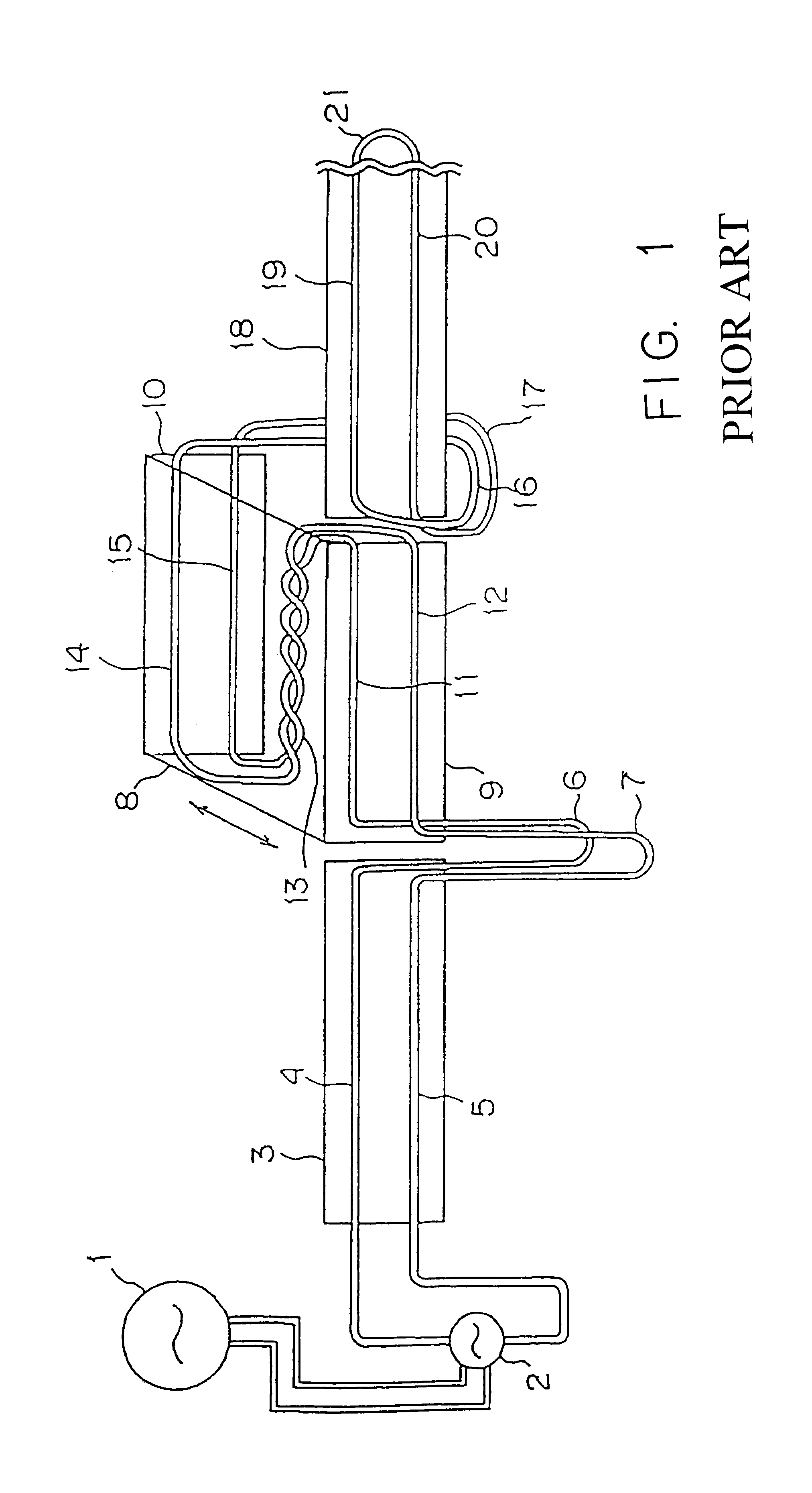
A commercial power source 1, a first high-frequency power supply source apparatus 2, a first fixed rail 3, feeder cables 4 and 5, a lateral table 8, first and second movable rails 9 and 10, feeder cables 11, 12, 14, and 15, a second fixed rail 18, feeder cables 19 and 20, and a short circuit line 21 are the same items as depicted in FIG. 1.

A secon...


PUM


Abstract

A non-contact electric power supply system for a rail-guided vehicle includes a main line having fixed rails for guiding the vehicle. A movable rail body is provided for changing the course of the vehicle moving along the main line. A first high frequency power supply apparatus supplies electric power to the main line along an electric feed line. A second high frequency power supply apparatus supplies electric power to the movable rail body along an electric feed line. Portions of the electric feed line on the movable rail body may be fixed in place.

Description

BACKGROUND OF THE INVENTION1. Field of the InventionThe present invention relates to a non-contact electric power supply system for movable sections for a rail-guided vehicle. More specifically, the present invention relates to the configuration of a non-contact electric power supply system for the stable supply of electric power to a lateral table and a turntable for a rail-guided vehicle.2. Description of the Related ArtAn electric feed cable secured to a rail on a main line, which itself ordinarily is fixed in place, and an electric feed line provided at a branch point, a rotating body, and similar movable bodies in a conventional non-contact electric power supply system are connected to form one loop among all electric feed lines by means of a connecting line connecting the main line and the movable bodies.The overall configuration of a non-contact electric power supply system for a rail-guided vehicle, as embodied in the related art, is hereunder explained, utilizing FIG. 1.A c...

Claims


Application Information

Patent Timeline
Patent Type & Authority Patents(United States)
IPC IPC(8): B60L9/00B60L5/00H02J17/00
CPCB60L5/005B60L2200/26
Inventor ODACHI, YASUHARUTAKASAN, MASAKIMORITA, KATSUYUKI
Owner TOYOTA IND CORP
Why Eureka
Try Eureka