Shrouded fluid-conducting apparatus

Inactive Publication Date: 2005-02-01
THE BOEING CO
View PDF12 Cites 129 Cited by
  • Summary
  • Abstract
  • Description
  • Claims
  • Application Information

AI Technical Summary

Benefits of technology

In one form, the present invention provides a shrouded fluid-conducting apparatus that includes at least one outer conduit and at least one inner conduit disposed within the outer conduit. Preferably, the shrouded fluid-conducting apparatus further includes at least one shrouded end fitting disposed at an end of the shrouded fluid-conducting apparatus and at least one support member engaged with the inner and outer conduits. The shrouded

Problems solved by technology

To summarize, the FAA regulations ensure that no single failure will jeopardize safe operation of the aircraft, as would be the case if single-wall fuel manifolds were used in aircraft “ignition zones.” That is, a leak or rupture in a single-wall fuel manifold would allow fuel to enter the “ignition zone”, which could result in catastrophic event were the fuel to ignite or explode.
Due to space limitations aboard aircraft, however, the relatively large outside diameter required for the outer tube has rendered this hose-in-tube concept impracticable.
Accordingly, the inner tube in this concept is unable to transfer loads to the outer tube and / or to components external thereto and is thus not viable.

Method used


Image

  • Shrouded fluid-conducting apparatus
  • Shrouded fluid-conducting apparatus
  • Shrouded fluid-conducting apparatus

Examples


second embodiment

FIGS. 5, 6 and 7 are each perspective views of a shrouded fluid-conducting apparatus 110 in which a portion 146 thereof that is disposed below the support member 120 is shown in respective first, second, and third positions 148, 150, 152. The portion 164 of the shrouded fluid-conducting apparatus 110 disposed above the support member 120 is shown to be essentially in the same position in FIGS. 5 through 7.

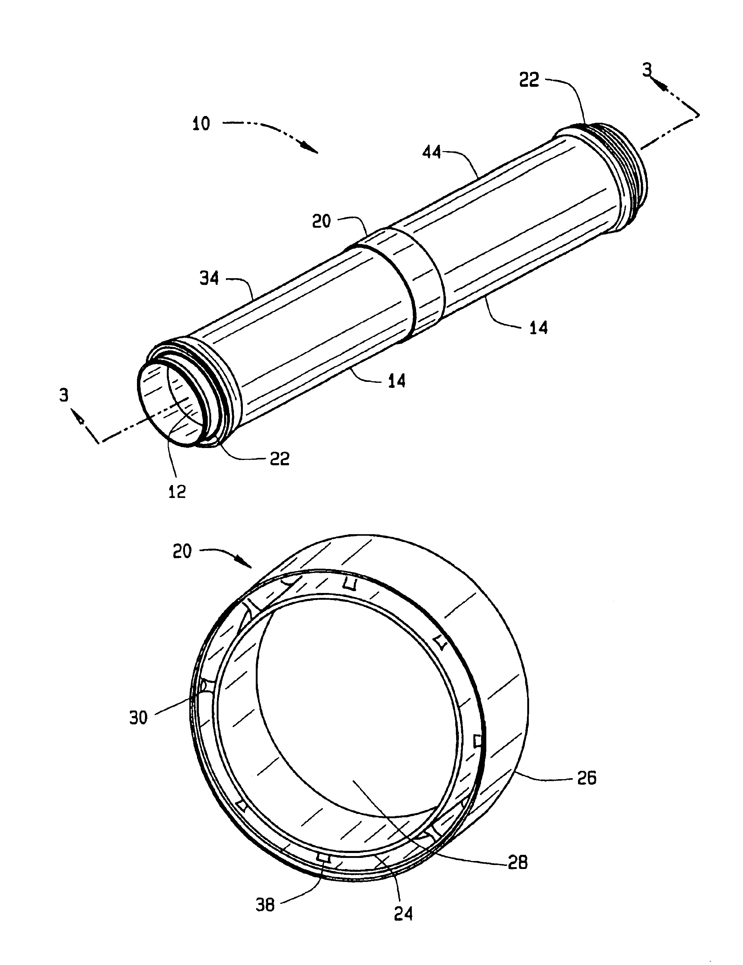
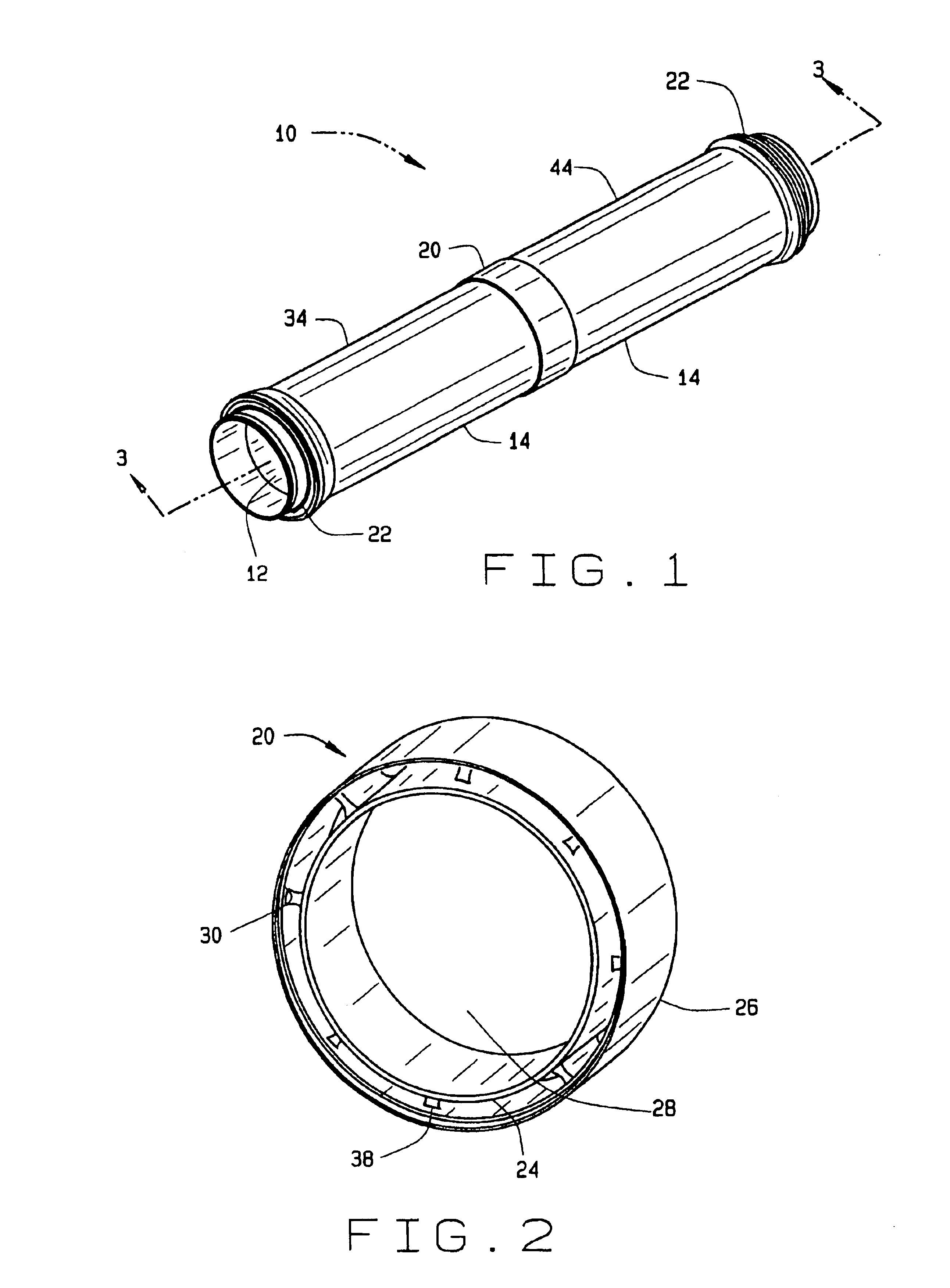
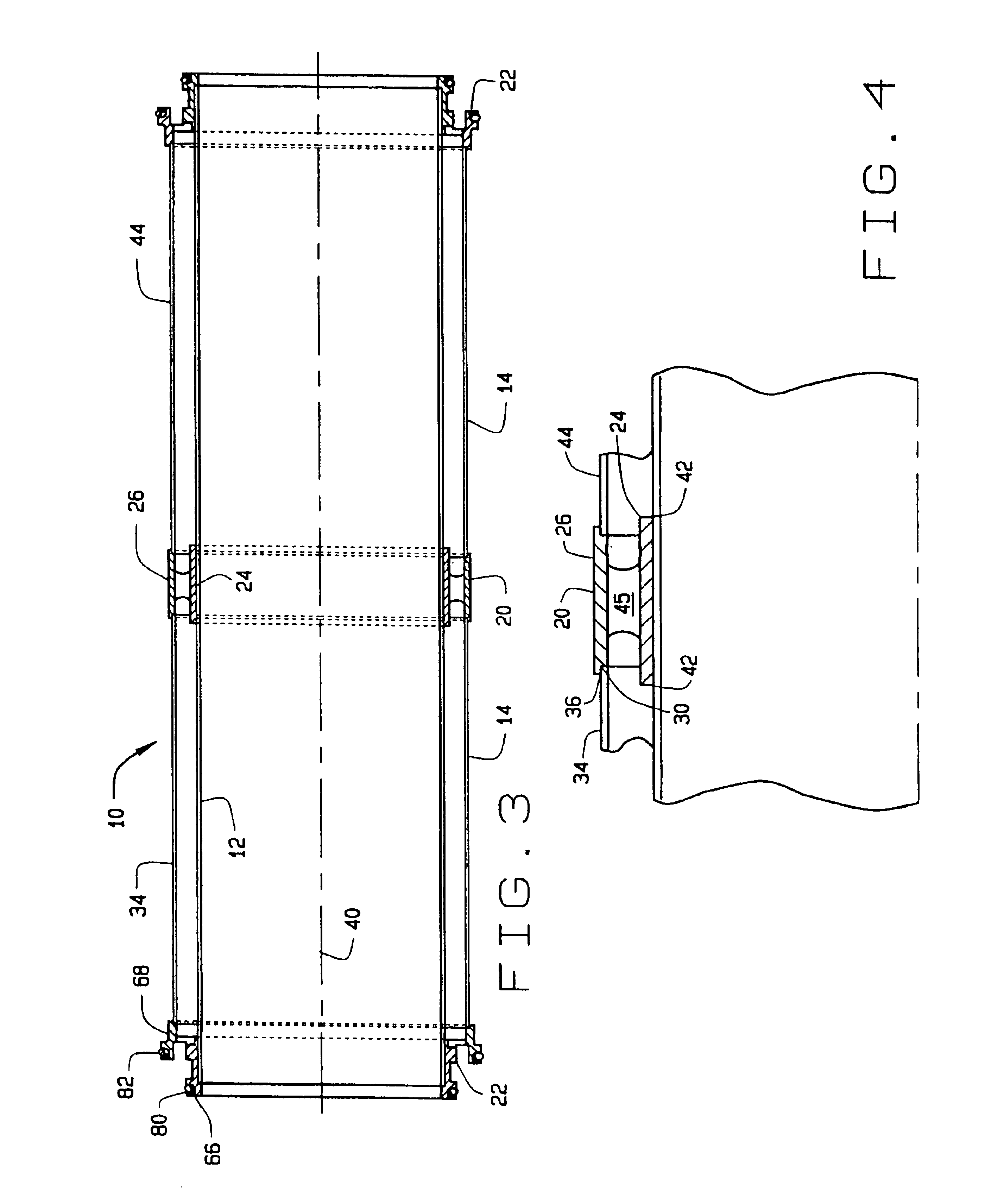
The shrouded fluid-conducting apparatus 110 includes curved or bent inner and outer conduits 112 and 114. To accommodate for the curvatures in the inner and outer conduits 112 and 114, the second embodiment of the support member 120 is used. The support member 120 allows for curvature or flexure of the shrouded fluid-conducting apparatus 110 in the manner that is described in detail below. Accordingly, the shrouded fluid-conducting apparatus 110 may be used, for example, at corners or other locations where flexure or curvature is required.

FIG. 8 is a perspective view of the support...

first embodiment

FIG. 13 is a perspective view showing the joint 84 that may be used to engage the shrouded fluid-conducting apparatus 10 with an additional shrouded fluid-conducting apparatus 10′. The joint 84 may be relatively flexible to allow for expansion and contraction of the joint 84 as the need arises. For example, the shrouded fluid-conducting apparatus 10 and 10′ may be disposed onboard a mobile platform (e.g., aircraft, train, bus, ship, etc.) wherein movement of the platform causes the need for at least some flexibility in the joint 84.

By allowing the shrouded fluid-conducting apparatus 10 to be engaged with additional shrouded fluid-conducting apparatus 10′, greater flexibility is provided to the installer of the overall fluid-conducting system. During the installation process of a fluid-conducting system, tight places and corners are often encountered that require the installer to use shorter components. At such locations, the installer may use one or more shorter length shrouded flui...

fourth embodiment

In the shrouded fluid-conducted apparatus that is not shown, the shrouded fluid-conducting apparatus may include the support member 120 and the shrouded end fittings 222 and 223.

It should be noted that any of the aforementioned embodiments of the shrouded fluid-conducting apparatus 10, 110, 210 may be used to provide a coaxial fluid flow. That is, the inner and outer conduits 12, 112 and 14, 114 of the shrouded fluid-conducting apparatus 10, 110, 210 may both be used to transport fluids at the same time. Moreover, the fluids being conducted by the inner conduit 12, 112 and the outer conduit 14, 114 may be either the same fluid or different fluids. In addition, the fluids may be conducted in either the same or different directions. For example, the inner conduit 12 of the shrouded fluid-conducting apparatus 10 may be used as fluid supply conduit, while the outer conduit 14 is used as a fluid return conduit.

Dimensionally, in one preferred embodiment, the inner conduit 12 is sized such...


PUM

PropertyMeasurementUnit
Distanceaaaaaaaaaa

Abstract

A shrouded fluid-conducting apparatus is provided that includes at least one outer conduit and at least one inner conduit disposed within the outer conduit. Preferably, the shrouded fluid-conducting apparatus further includes at least one shrouded end fitting disposed at an end of the shrouded fluid-conducting apparatus and at least one support member engaged with the inner and outer conduits. The shrouded end fitting allows the shrouded fluid-conducting apparatus to be engaged with an additional shrouded fluid-conducting apparatus. The support member allows for the transfer of loads from the inner and / or outer conduits to one or more components external to the shrouded fluid-conducting apparatus. Accordingly, the shrouded-fluid conducting apparatus may be used to transport fuel through an aircraft “ignition zone” in an FAA-compliant manner.

Description

FIELD OF THE INVENTIONThe present invention relates generally to fluid-conducting apparatus and more particularly to methods and apparatus for conducting fuel in aircraft.BACKGROUND OF THE INVENTIONAccording to Federal Aviation Administration (FAA) regulations, fuel lines (e.g., manifolds, conduits) that conduct or transport fuel through areas classified by the FAA as “ignition zones” (e.g., pressurized areas) must be shrouded and capable of being drained. The applicable sections of the FAA requirements relative to fuel lines in aircraft ignition zones for transport category airplanes are contained in 14 C.F.R. Part 25, the pertinent parts of which are set forth below.For example, Section 25.855 states in pertinent part that “for each cargo and baggage compartment not occupied by crew or passengers . . . no compartment may contain any controls, wiring, lines, equipment, or accessories whose damage or failure would affect safe operation, unless those items are protected so that . . ....

Claims


Application Information

Patent Timeline
IPC IPC(8): F16L39/00
CPCF16L39/005F16L23/167F16L25/01Y10T29/53443B64D37/005B64D37/32Y10T29/49826F16L2201/30H01R4/643
Inventor CARNS, JAMES A.CUTLER, THERON L.SHELLY, MARK A.
Owner THE BOEING CO
Why Eureka
Try Eureka