Piping unit for transporting fuel

a fuel transporting and piping technology, applied in the direction of hose connection, pipe coupling, coupling, etc., can solve the problem of hard to break the resin tube, and achieve the effect of easy connection and hard to break

Active Publication Date: 2013-09-17
SUMITOMO RIKO CO LTD
View PDF59 Cites 6 Cited by
  • Summary
  • Abstract
  • Description
  • Claims
  • Application Information

AI Technical Summary

Benefits of technology

The invention is a new kind of piping unit that uses a resin tube as a main component. This makes it easy to connect the piping unit to other pipes without needing metal fittings. The resin tube is also strong enough to withstand bending forces. The technical effect of this invention is to provide a more efficient and durable piping system for motor vehicle bodies.

Problems solved by technology

And, for example, the resin tube is hard to be broken when a bending force is exerted thereto.

Method used


Image

  • Piping unit for transporting fuel
  • Piping unit for transporting fuel
  • Piping unit for transporting fuel

Examples


example

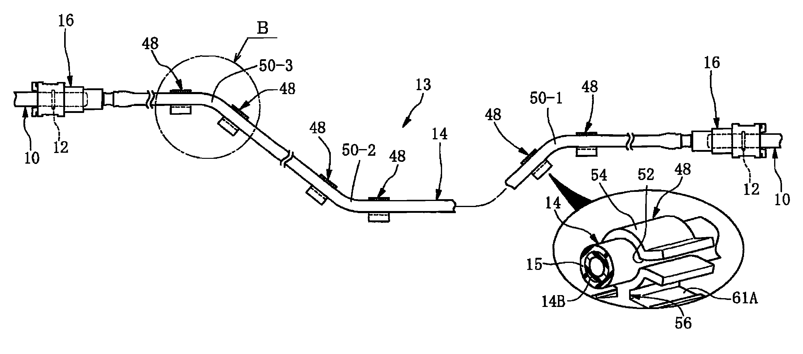
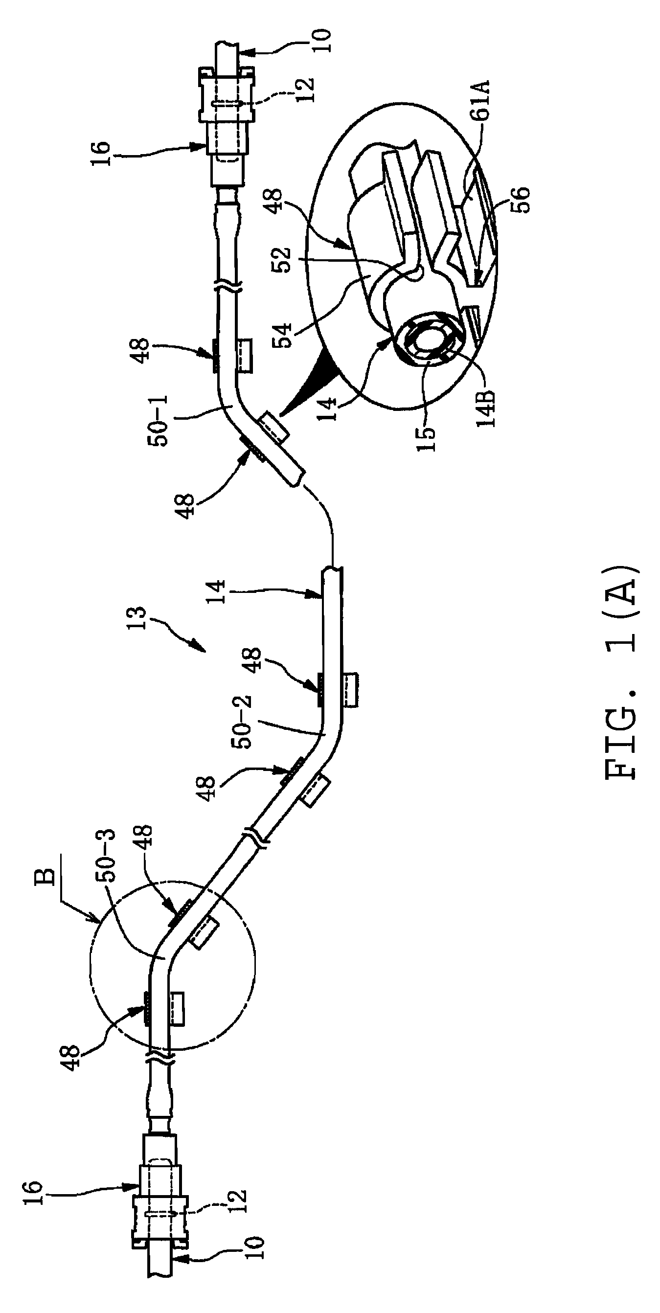
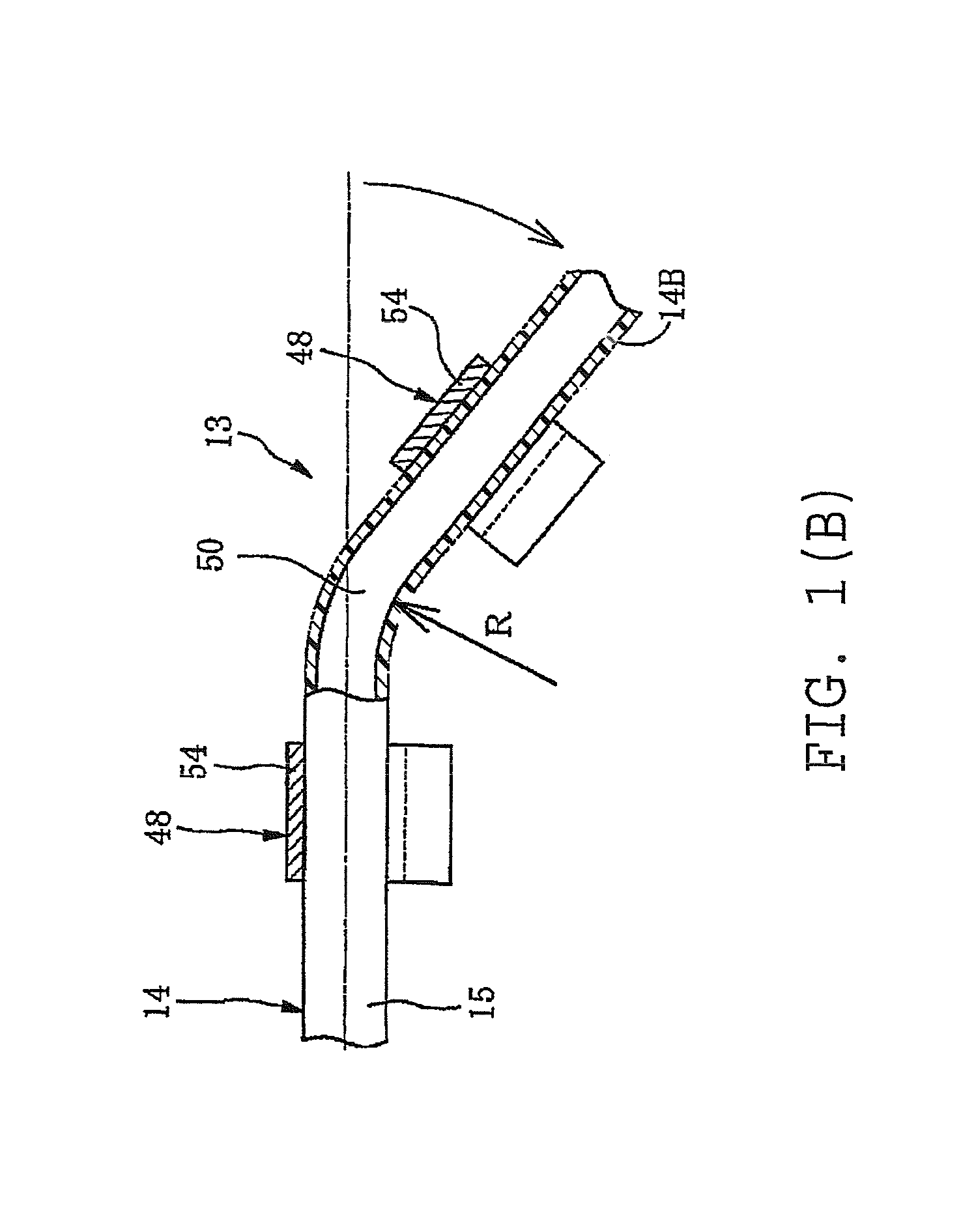
[0184]A test is conducted in a following procedure with respect to examples and comparison examples of the resin tube 14 in order to clarify a relationship between the bending breaking resistance and a ratio of an outer diameter (od) / a wall-thickness (t)(wall-thickness ratio) in the resin tube 14.

[0185]Here, examples and comparison examples of resin tube 14 have the same outer diameter (od) of 4 mm (except for comparison example No. 6), but varied wall-thickness (t). Each of them is bent at 900, while being held at both ends by the fixing clamps 48, 48.

[0186]Then, the fixing clamps 48, 48 are rearranged a shorter distance apart on each of them to hold it. And, each of them is bent again at 90° in a similar way, while being held by the fixing clamps 48, 48.

[0187]The above is repeated until the resin tube is broken (buckled or kinked), and searched is a minimum bend R (radius or curvature radius) that does not cause breakage with respect to each of the samples and the comparison sampl...


PUM


Abstract

Piping unit for transporting a fuel is constructed by connecting a resin tube and a connector for connecting the resin tube to a mating pipe. The connector has a connector body including a retainer holding portion and a retainer for engaging with the mating pipe. The resin tube has a multilayered construction including an inner fuel barrier layer and an outer layer covered with a protective layer. The outer layer has a small outer diameter (od) up to 6 mm, the fuel barrier layer and the outer layer have a wall-thickness (t), and a ratio of the outer diameter (od) / the wall thickness (t) is in a range of 4 to 8.

Description

CROSS-REFERENCE TO RELATED APPLICATIONS[0001]The present application is a divisional of co-pending U.S. patent application Ser. No. 11 / 304,386, filed Dec. 15, 2005, now abandoned, which application is incorporated herein by reference and which application claims priority of Japanese Patent Application No. 2004-366653, filed Dec. 17, 2004, and Japanese Patent Application No. 2005-342038, filed Nov. 28, 2005, which applications are incorporated herein by reference.BACKGROUND OF THE INVENTION[0002]1. Field of the Invention[0003]The present invention relates to a piping unit installed between an engine and a fuel tank to transport a fuel.[0004]2. Description of the Related Art[0005]Recently, as a control on exhaust emissions is tighten, a fuel injection system (injection system) of high fuel efficiency has been employed even in a compact vehicle with a small engine such as mini-vehicle, two-wheeled motor vehicle, three-wheeled motor vehicle, and all-terrain vehicle (ATV).[0006]In this f...

Claims


Application Information

Patent Timeline
Patent Type & Authority Patents(United States)
IPC IPC(8): B60D1/62
CPCB32B1/08B32B25/16B32B27/08B32B27/322B32B27/34F16L3/12F16L3/127F16L11/04F16L33/30F16L37/0985B32B25/08Y10T428/1393B32B2250/03B32B2250/24B32B2274/00B32B2307/54B32B2307/558B32B2307/7265B32B2597/00B32B2605/00F16L2011/047F16L2201/10Y10T137/9029
Inventor INOUE, TOMOKISASAGAWA, MASAYUKI
Owner SUMITOMO RIKO CO LTD
Why Eureka
Try Eureka