Novel radial cyclone with wave type blades

A swirler and wave-type technology, applied in the field of components, to achieve the effect of sufficient oil and gas mixing, improved airflow conditions, and longer distances

Inactive Publication Date: 2019-03-29
NORTHWESTERN POLYTECHNICAL UNIV
View PDF6 Cites 7 Cited by
  • Summary
  • Abstract
  • Description
  • Claims
  • Application Information

AI Technical Summary

Problems solved by technology

Each modification requires a new casting process as well as casting machining

Method used


Image

  • Novel radial cyclone with wave type blades
  • Novel radial cyclone with wave type blades
  • Novel radial cyclone with wave type blades

Examples


Embodiment Construction

[0018] The present invention will be further described now in conjunction with accompanying drawing:

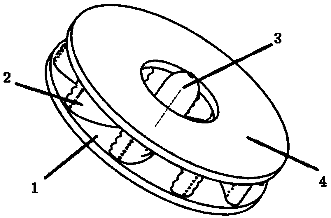
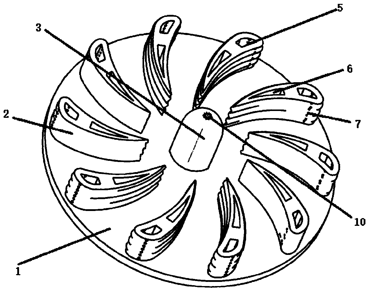
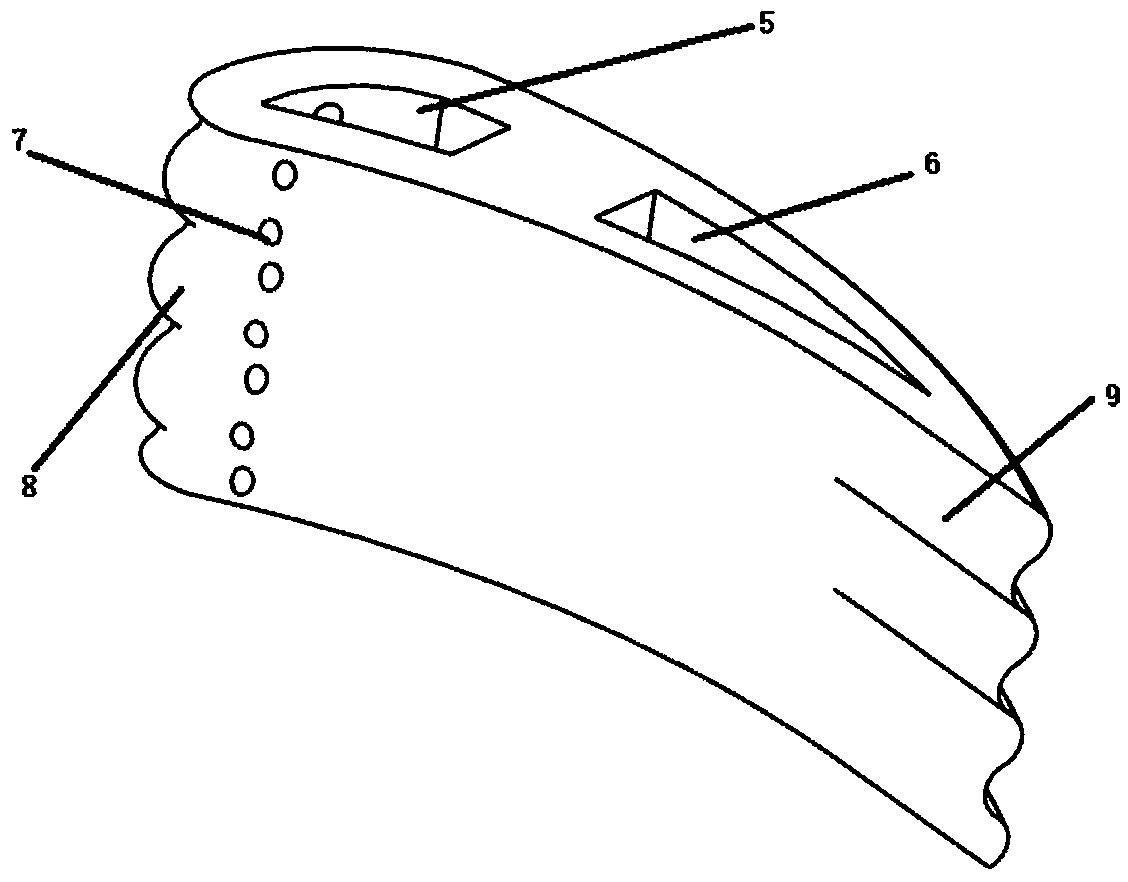
[0019] combine figure 1 , figure 2 , image 3 , The present invention provides: The present invention proposes a novel radial swirler with wavy blades, which can effectively improve the flow distribution of air flow and the mixing of oil and gas, and generate stable high-quality gas mixture and swirl vortex. figure 1 It is a structural schematic diagram of the radial swirler of the present invention, the radial swirler front baffle (1), wave blades (2), center spout (3), rear baffle (4); figure 2 is the radial swirler vane distribution diagram, image 3 It is a schematic diagram of the blade structure of the radial swirler, and the structure of the wavy blade can be clearly seen, including the blade front cavity (5), the blade rear cavity (6), and the blade front edge nozzle (7).

[0020] The front baffle plate (1) and the rear baffle plate (4) of the radial swirler are...


PUM


Abstract

In order to solve the technical problems, the invention discloses a novel radial cyclone with wave type blades. The combustion chamber cyclone comprises multiple blades, cyclone front and rear baffleplates and a bullet shaped centre cone. The radial cyclone is simple in structure, is convenient in manufacturing, and is suitable for being matched with gas-flow flowing in front of a combustion chamber; gullies are arranged on the surfaces of the blades in a wavy mode; the blades are internally equipped with cavities axially, which are separated from one another for conveying and transporting fuel oil; and the tail parts of the blades are in the shapes of sine waves, so that the rotational-flow effect is effectively improved, and therefore, fuel gas and air are mixed more uniformly to form agas mixture with better quality.

Description

technical field [0001] The invention relates to a component of a gas turbine, in particular to a novel radial swirler with wavy blades. Background technique [0002] In a gas turbine engine, the air is compressed by the compressor, and mixed with fuel in the combustion chamber to generate a hot gas flow flowing downstream, and passes through the turbines at various levels for extracting energy. The high-pressure turbine drives the compressor, and the low-pressure turbine drives the fan. For example, useful work is done by the upstream fan in a typical aviation turbofan gas turbine engine. The performance of the combustion chamber is very important to the overall performance of the gas turbine engine. Compressed air is mixed with fuel in the combustion chamber to become a mixture of fuel and air, and then ignited and burned to generate gas. The vortex flow in the gas turbine combustor is used to stabilize the flame and promote the mixing of fuel and air. Therefore, the vorte...

Claims


Application Information

Patent Timeline
Patent Type & Authority Applications(China)
IPC IPC(8): F23R3/58F23R3/38
CPCF23R3/38F23R3/58
Inventor 张群曹婷婷杨福正李程镐刘强王鑫海涵张鹏
Owner NORTHWESTERN POLYTECHNICAL UNIV
Why Eureka
Try Eureka