
Actuator for an automatic transmission provided with electrical actuation

Inactive Publication Date: 2005-02-01
KONGSBERG AUTOMOTIVE AB (SE)
View PDF13 Cites 0 Cited by
  • Summary
  • Abstract
  • Description
  • Claims
  • Application Information

AI Technical Summary

Benefits of technology

Therefore, it is the object of the invention to eliminate the disadvantages of the prior art and to provide an actuator for an automatic transmission by which very high forces can be transmitted to the automatic transmission on the one hand and in which it is possible, on the other hand, to carry out positioning very precisely and quickly, wherein a drive with low weight and compact dimensioning is to be used.
Further, it is advantageous to couple the electric motor with a self-locking worm gear unit so that the gear unit acts on the four-bar linkage transmission. This is required for reducing the rotational speed of the electric motor.
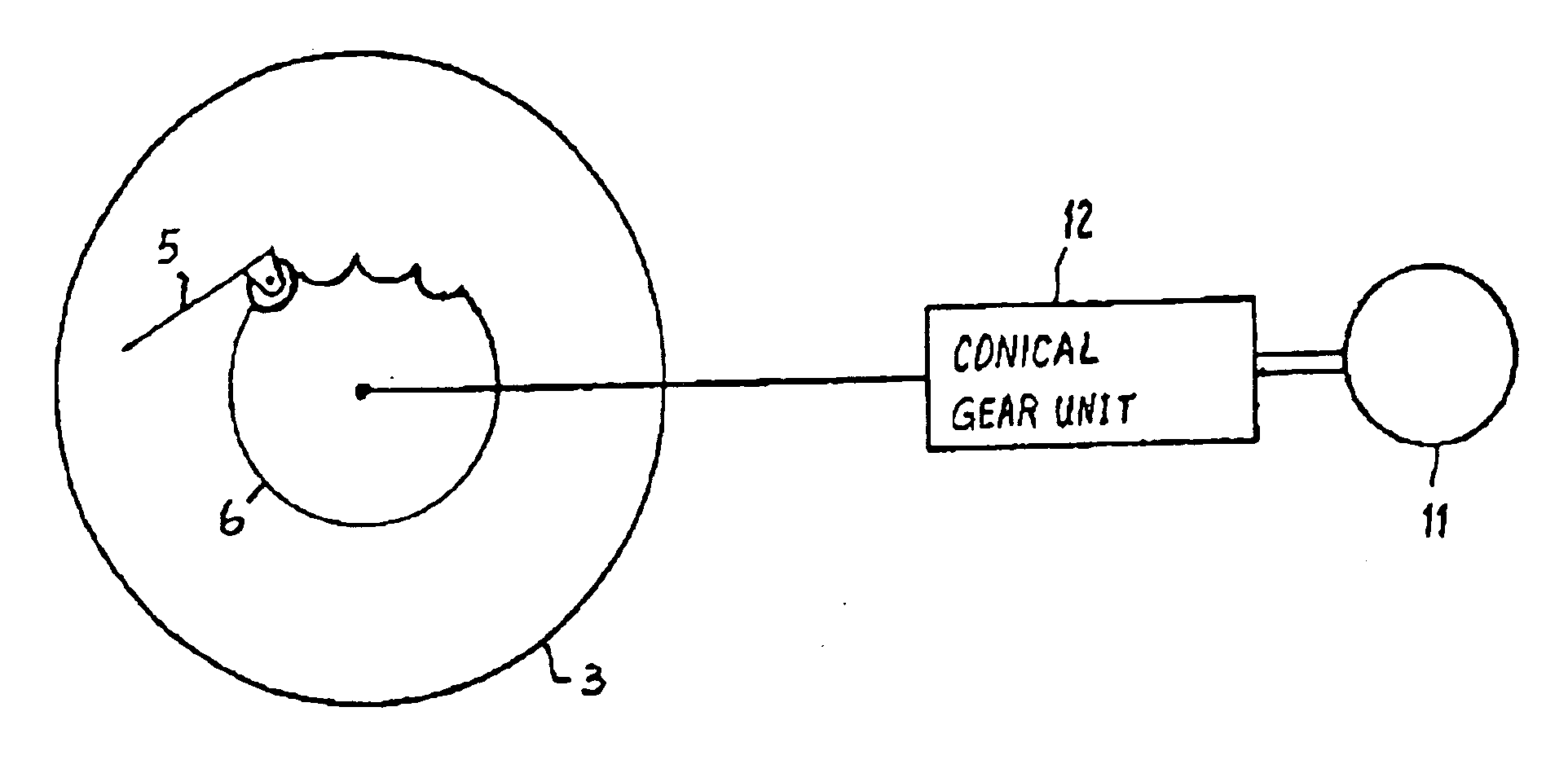
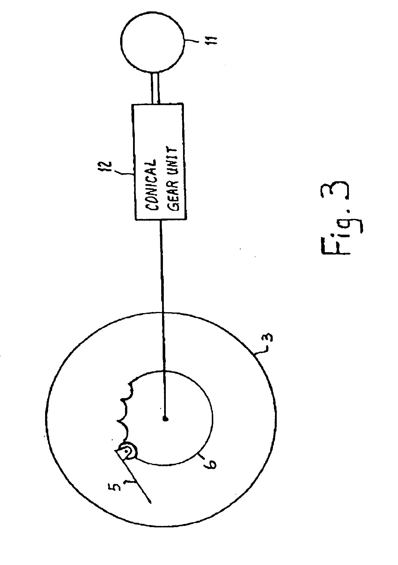
Instead of the four-bar linkage transmission, the invention can also be realized by other gear units with transmission ratios that are not constants, e.g., planetary gear units, toothed rack gear units or conical gear units. This makes it possible to transmit high forces to the automatic transmission with the low-output drive in favor of a long path.

Problems solved by technology

Therefore, a very high expenditure of energy is needed to remove the transmission from the “P” gear position.
For vehicles with an electrically actuated automatic transmission, this means that the electric drive in question must be designed with a distinctly high output; however, as a result of this, the drive responds very sluggishly and is very heavy.
Moreover, drives of this type occupy a large amount of space and are expensive.
A powerful and sluggish drive such as that in large electric motors is unsuitable for these tasks.
Since the tolerance chain between selection actuation and transmission is too large for precise positioning with mechanical actuation, play is required between the drive and transmission.
This is problematic precisely with steep grades, e.g., garage entrances, with grades of up to 30 percent.
The disadvantage of this arrangement is that no higher forces can be transmitted via the electric motor, which is a stepper motor.

Method used


Image

  • Actuator for an automatic transmission provided with electrical actuation
  • Actuator for an automatic transmission provided with electrical actuation
  • Actuator for an automatic transmission provided with electrical actuation

Examples


Embodiment Construction

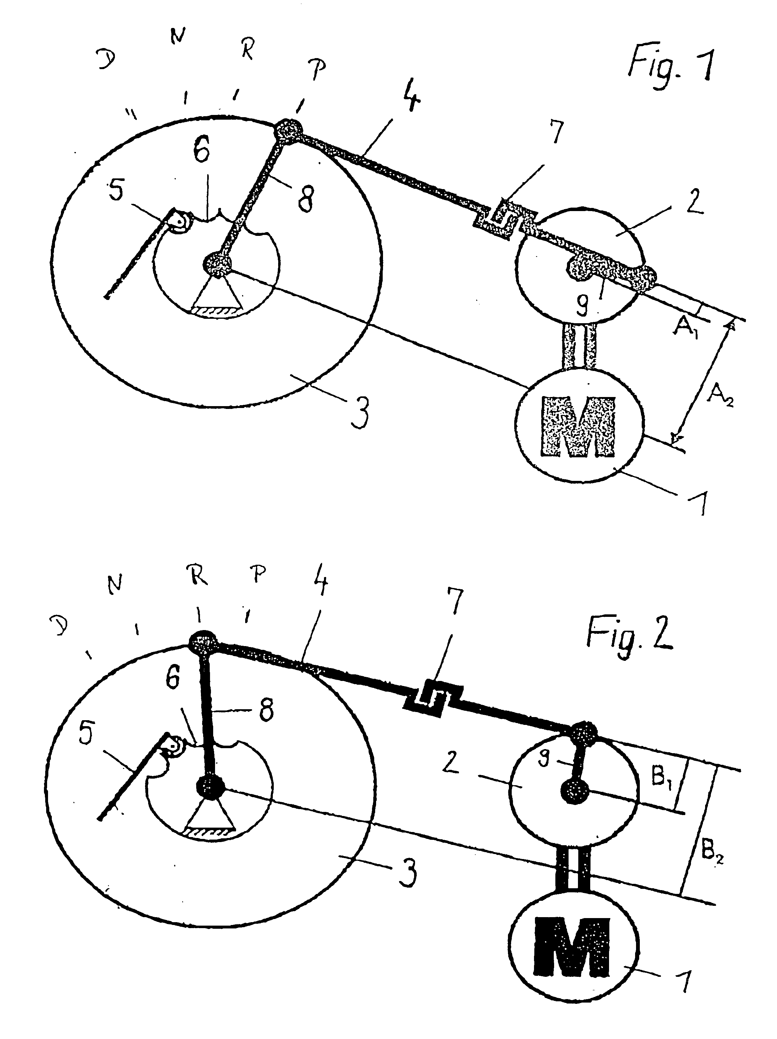
FIG. 1 shows the actuator of an electric actuating device of an automatic transmission according to the invention, whose electric drive 1 comprises a relatively small motor 1 which does not have a very high output. This motor 1 is coupled with the self-locking worm gear unit 2. The vehicle which is in the parked position and which has been parked on a slope has exerted a force on the transmission, in the present case on the automatic transmission 3, due to the descending force of the slope. Because of the inclined position, a high force is required after parking to remove the detent from the parking ratchet wheel again. The four-bar linkage transmission is designed in such a way that the cranks 8, 9 at the automatic transmission 3 and at the worm gear unit 2 are rotated relative to one another via the coupling rod 4 in the parked position such that the coupling rod 4 assumes a very acute angle with the crank 9 at the worm gear unit 2. The lever ratios between A1 and A2 are according...


PUM


Abstract

An electrical actuation for an automatic transmission, preferably for selection actuation in automobiles in which a four-bar linkage transmission and a worm gear unit are arranged between the electric drive and the transmission. Shifting can be carried out with a low-output drive, particularly in the parked shifting position “P”, also when very large forces are required such as those occurring when the vehicle is parked on a hill.

Description

BACKGROUND OF THE INVENTION1. Field of the InventionThe invention relates to an actuator for an automatic transmission provided with electrical actuation, preferably for automobiles.The solution according to the invention is suitable for automatic transmissions, especially for automobiles which are often parked on inclined surfaces in the driving direction.2. Discussion of the Prior ArtThe object of the selection actuation in an automobile is to convey the gear setting adjusted by the driver to the transmission. It is possible to do this mechanically or electrically. With electrical selection actuation in the driver's compartment of the vehicle, the selection actuation is only an electric switch or sensor which conveys the gear selected by the driver to the transmission controller. The selection actuation can be constructed as a conventional lever. However, it can also be realized as a rotary switch or by means of push buttons.The transmission controller contains a microprocessor wh...

Claims


Application Information

Patent Timeline
IPC IPC(8): F16H61/28F16H61/32F16H59/08
CPCF16H61/32F16H59/08Y10T74/2003Y10T74/19251F16H2061/326
Inventor BENDA, THOMAS
Owner KONGSBERG AUTOMOTIVE AB (SE)
Learn More