Basic cells configurable into different types of semiconductor integrated circuits
a technology of integrated circuits and basic cells, applied in logic circuits using elementary logic circuit components, logic circuits using specific components, pulse techniques, etc., can solve the problems of inability to finely adjust vth and tpd, low frequency of use of nmos transistors, poor usage efficiency of elements within basic cells, etc., to achieve the effect of reducing the size of the overall circuit, reducing labor, and eliminating the labor
- Summary
- Abstract
- Description
- Claims
- Application Information
AI Technical Summary
Benefits of technology
Problems solved by technology
Method used
Image
Examples
first embodiment
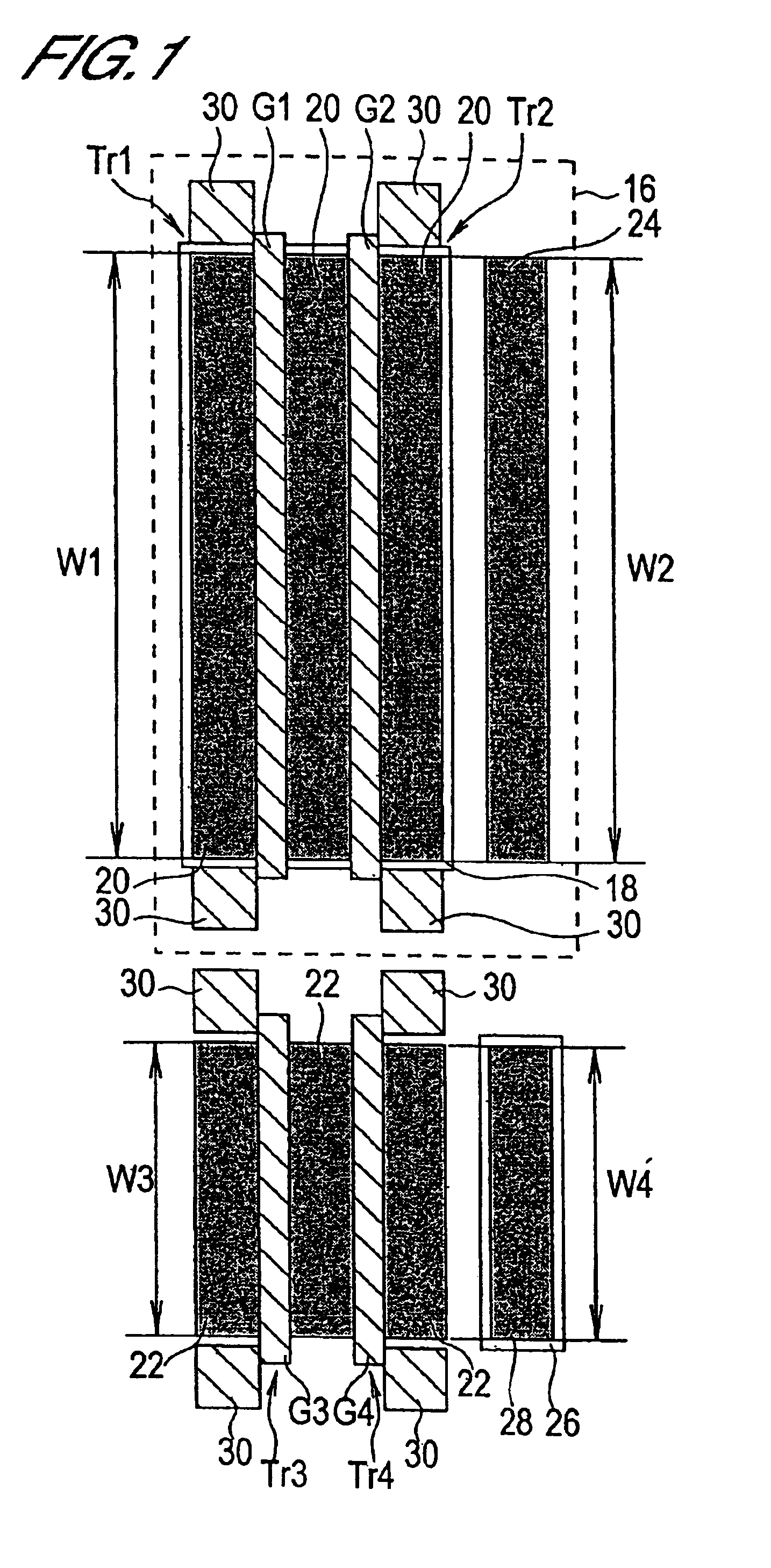
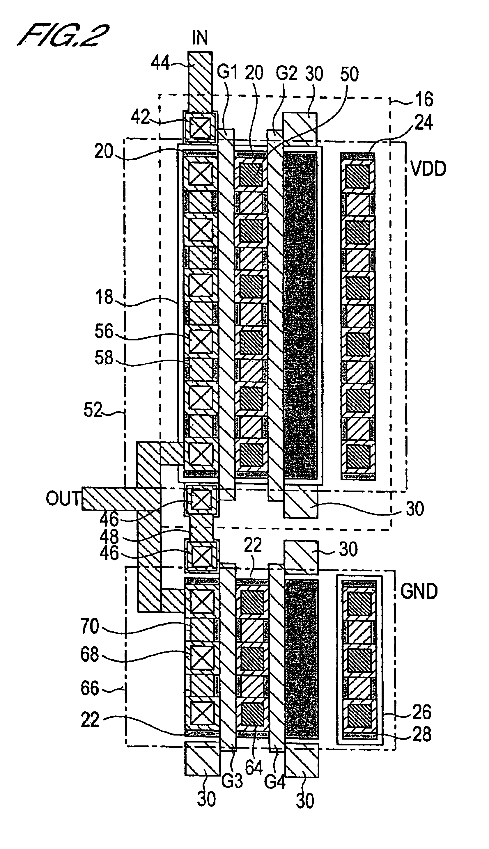
FIG. 1 is a mask pattern diagram of a basic cell comprised by a semiconductor integrated circuit of a first embodiment of this invention. The basic cell shown in FIG. 1 comprises a first P-channel MOS (hereafter “PMOS”) transistor Tr1, a second PMOS transistor Tr2, a first N-channel MOS (hereafter “NMOS”) transistor Tr3, and a second NMOS transistor Tr4.
Each of the transistors Tr1 through Tr4 is formed on P-type Si substrate, not shown. PMOS transistors Tr1 and Tr2 are formed within an N-well 16 formed in the substrate. Within this N-well 16, a P-type semiconductor region 18 is formed. Within this P-type semiconductor region 18, the active regions 20 of the PMOS transistors Tr1 and Tr2 are formed. Also, two parallel stripe-shape polysilicon films are formed on these active regions 20 as the gates G1 and G2 of the PMOS transistors Tr1 and Tr2.
Adjacent to the N-well 16, the active regions 22 of the NMOS transistors Tr3 and Tr4 are formed. On these active regions 22, two parallel strip...
second embodiment
FIG. 9 is a mask pattern diagram showing a basic cell comprised by the semiconductor integrated circuit of a second embodiment. The basic cell shown in FIG. 9 comprises a first PMOS transistor Tr1, a second PMOS transistor Tr2, a third PMOS transistor Tr3, a first NMOS transistor Tr4, and a second NMOS transistor Tr5.
Each of the transistors Tr1 through Tr5 is formed on P-type Si substrate, not shown. PMOS transistors Tr1, Tr2 and Tr3 are formed within an N-well 16 formed in the substrate. Within this N-well 16, a P-type semiconductor region 18 is formed. Within this P-type semiconductor region 18, the active regions 20 of the PMOS transistors Tr1, Tr2 and Tr3 are formed. Also, two parallel stripe-shape polysilicon films are formed on these active regions 20 as the gates G1, G2 and G3 of the PMOS transistors Tr1, Tr2 and Tr3. One of the polysilicon films is used as the gate G1 of PMOS transistor Tr1, and the other polysilicon film is used as the gates G2 and G3 of PMOS transistors Tr...
third embodiment
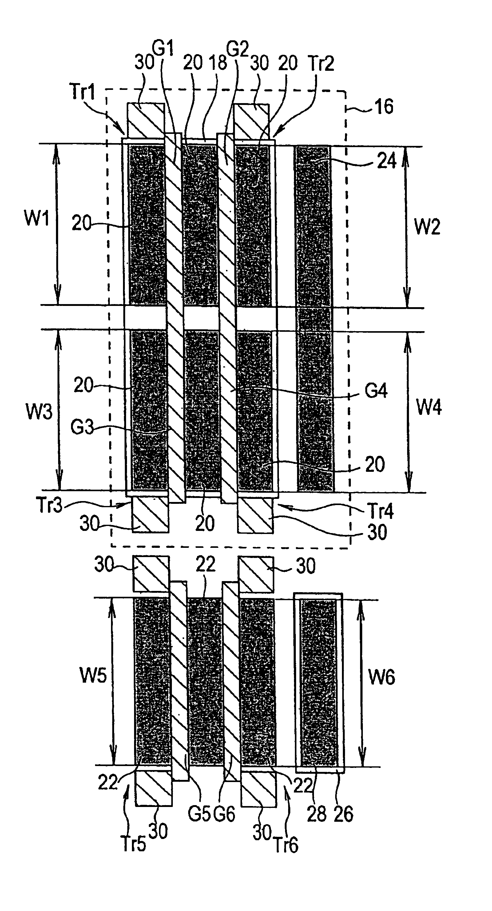
FIG. 14 is a mask pattern diagram showing a basic cell comprised by the semiconductor integrated circuit of a third embodiment. The basic cell shown in FIG. 14 comprises a first PMOS transistor Tr1, a second PMOS transistor Tr2, a third PMOS transistor Tr3, a fourth PMOS transistor Tr4, a first NMOS transistor Tr5, and a second NMOS transistor Tr6.
Each of the transistors Tr1 through Tr6 is formed on P-type Si substrate, not shown. PMOS transistors Tr1 through Tr4 are formed within an N-well 16 formed in the substrate. Within this N-well 16, a P-type semiconductor region 18 is formed. Within this P-type semiconductor region 18, the active regions 20 of the PMOS transistors Tr1 through Tr4 are formed. Also, two parallel stripe-shape polysilicon films are formed on these active regions 20 as the gates G1, G2, G3 and G4 of the PMOS transistors Tr1 through Tr4. One of the polysilicon films is used as the gates G1 and G3 of PMOS transistors Tr1 and Tr3, and the other polysilicon film is u...
PUM
 Abstract
Description
Claims
Application Information
 - R&D
- Intellectual Property
- Life Sciences
- Materials
- Tech Scout
- Unparalleled Data Quality
- Higher Quality Content
- 60% Fewer Hallucinations
Browse by: Latest US Patents, China's latest patents, Technical Efficacy Thesaurus, Application Domain, Technology Topic, Popular Technical Reports.
© 2025 PatSnap. All rights reserved.Legal|Privacy policy|Modern Slavery Act Transparency Statement|Sitemap|About US| Contact US: help@patsnap.com


