Head rail-mounted actuator for window coverings

a head rail and actuator technology, applied in the direction of light control, dynamo-electric motor/converter starter, light control, etc., can solve the problems of consuming a relatively large amount of power, affecting the operation of automatic blind control systems, and being difficult to opera

Inactive Publication Date: 2005-02-01
HARMONIC DESIGN INC FORMERLY SOMFY ACQUISITION
View PDF10 Cites 67 Cited by
  • Summary
  • Abstract
  • Description
  • Claims
  • Application Information

AI Technical Summary

Benefits of technology

A sensor is provided for detecting a light signal and generating a control signal in response thereto. Also, a coupling is engageable with the rod such that movement of the coupling causes rotation of the rod. Further, a reversible electric direct current (dc) motor is operably engaged with the coupling to move the coupling, and a dc battery is electrically connected to the motor. An electronic circuit is electrically connected to the light sensor and the battery for processing the control signal from the light sensor to cause the battery to energize the motor.
Preferably, at least a first travel limiter is positioned in the head rail to cause the motor to be deenergized when the rod reaches a predetermined position. Moreover, a limit switch is electrically connected to the electronic circuit and is positioned adjacent the first travel limiter, so that the first travel limiter can contact the limit switch and thereby cause the electronic circuit to deenergize the motor. Desirably, a second travel limiter is positioned in the head rail for contacting the limit switch, so that the second travel limiter can contact the limit switch and thereby cause the electronic circuit to deenergize the motor. Or, an overcurrent sensor can be used to stop the motor at its limits of travel.

Problems solved by technology

Unfortunately, the systems mentioned above, like many, if not most, automatic blind control systems, are somewhat complicated in operation and cumbersome and bulky in installation, and consequently are relatively expensive.
The Ringle, III device consumes a relatively large amount of power to sense its control signal, and thus exhausts its battery quickly, in part because of its relatively complicated limit switch mechanism and because Ringle, III does not provide any electronic signal processing which would enable the Ringle, III device to sense a control signal efficiently, with little power consumption.

Method used


Image

  • Head rail-mounted actuator for window coverings
  • Head rail-mounted actuator for window coverings
  • Head rail-mounted actuator for window coverings

Examples


Embodiment Construction

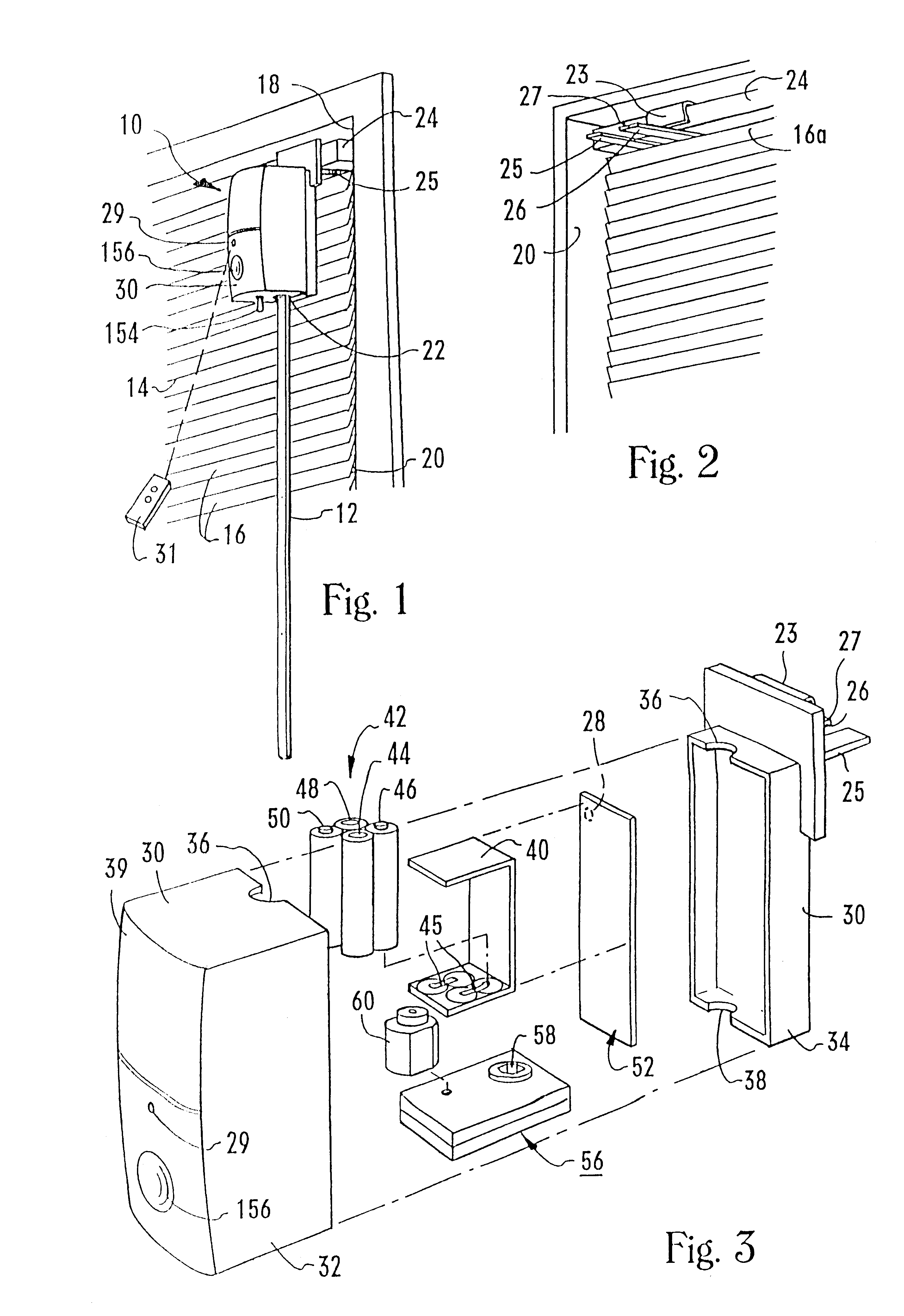
Referring initially to FIG. 1, an actuator is shown, generally designated 10. As shown, the actuator 10 is in operable engagement with a rotatable operating baton 12 of a mini-blind 14 having a plurality of louvered slats 16.

In the embodiment shown, the mini-blind 14 is a Levellor®-type mini-blind which is mounted on a window frame 18 to cover a window 20, and the baton 12 is rotatable about its longitudinal axis. When the baton 12 is rotated about its longitudinal axis, each of the slats 16 is caused to rotate about its respective longitudinal axis to move the mini-blind 14 between an open configuration, wherein a light passageway is established between each pair of adjacent slats, and a closed configuration, wherein no light passageways are established between adjacent slats.

While the embodiment described above discusses a mini-blind, it is to be understood that the principles of the present invention apply to a wide range of window coverings that have louvered slats.

As can be app...


PUM


Abstract

A mini-blind actuator has a motor and a housing that holds the motor and a dc battery. The rotor of the motor is coupled to the baton of the mini-blind for rotating the baton and thereby opening or closing the slats of the mini-blind. Alternatively, the rotor is coupled to the tilt rod of the blind to rotate the tilt rod and thereby open or close the slats of the mini-blind. A control signal generator generates a control signal for completing the electrical circuit between the battery and the motor. The control signal can be generated in response to a predetermined amount of daylight or in response to a user-generated remote command signal. The actuator can be used to rotate the slats of horizontal or vertical blinds, or the sections of a pleated shade. Or, the actuator can be used to rotate the hollow rotatable tube of a roll-up shade.

Description

FIELD OF THE INVENTIONThe present invention relates generally to window covering peripherals and more particularly to remotely-controlled window coverings.BACKGROUNDLouvered blinds, such as Levellor® mini-blinds, are used as window coverings in a vast number of business buildings and dwellings. The typical blind has a number of horizontal elongated parallelepiped-shaped louvers, i.e., rotationally-movable slats, which are collectively oriented with their major surfaces parallel to the ground (“open”) to permit light to pass between adjacent slats, or with their major surfaces perpendicular to the ground (“closed”), to block light from passing between adjacent slats, or any intermediate position between open and closed. Stated differently, the slats can be rotated about their respective longitudinal axes, i.e., about respective lines which are parallel to the ground, to open or close the blind. Alternatively, the slats may be oriented vertically for rotation about their respective lo...

Claims


Application Information

Patent Timeline
Patent Type & Authority Patents(United States)
IPC IPC(8): E06B9/36E06B9/32E06B9/26E06B9/307E06B9/28G05D25/00G05D25/02E06B9/68
CPCE06B9/307E06B9/32E06B9/364E06B9/368G05D25/02E06B9/68Y02B80/50E06B2009/285E06B2009/6827Y02B80/00Y02A30/24
Inventor DOMEL, DOUGLAS R.WALKER, WINSTON G.
Owner HARMONIC DESIGN INC FORMERLY SOMFY ACQUISITION
Why Eureka
Try Eureka