High-frequency phase shifter unit having pivotable tapping element

a high-frequency phase shifter and pivoting element technology, applied in waveguides, delay lines, antennas, etc., can solve the problems of changing the impedance of the respective affected lines, two radiating elements can be supplied, and moving electrically conductive connections between the input and the respective lines

Inactive Publication Date: 2005-02-01
TELEFON AB LM ERICSSON (PUBL)
View PDF219 Cites 84 Cited by
  • Summary
  • Abstract
  • Description
  • Claims
  • Application Information

AI Technical Summary

Benefits of technology

One simple exemplary implementation of the phase shift assembly can also allow the cir

Problems solved by technology

This has the disadvantage that the movement of the dielectric plates also changes the impedance of the respectively affected lines, and the way in which the power of the signals is shared depends on the setting of the phase shifter.
However, these solutions have the disadvantage t

Method used


Image

  • High-frequency phase shifter unit having pivotable tapping element
  • High-frequency phase shifter unit having pivotable tapping element
  • High-frequency phase shifter unit having pivotable tapping element

Examples


Embodiment Construction

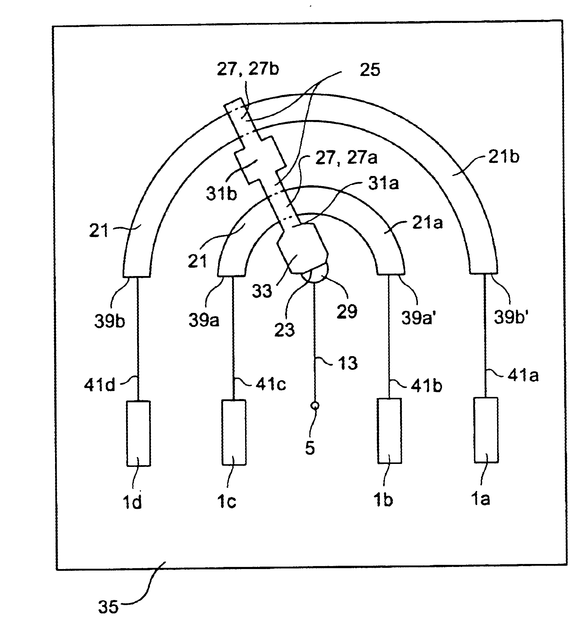
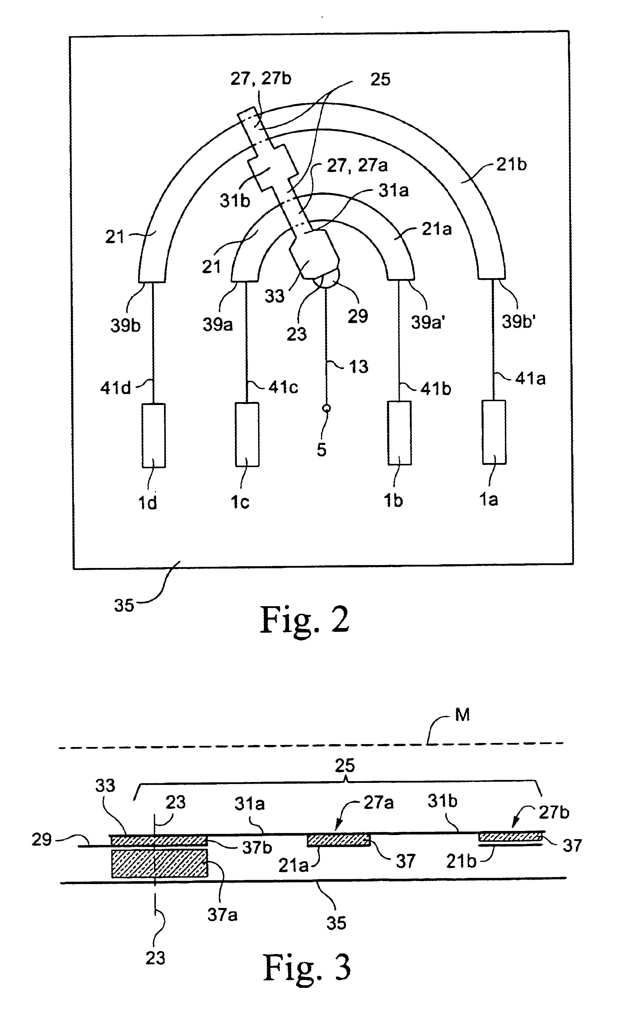
A first exemplary implementation of a radio-frequency phase shift assembly has stripline sections 21 offset with respect to one another as shown in FIG. 2. Stripline segments 21 are provided in the form of circle segments in the illustrated exemplary embodiment. An inner stripline segment 21a and an outer stripline segment 21b are arranged concentrically around a common center point in a plan view and through which a vertical pivoting axis 23 runs at right angles to the plane of the drawing.

A tapping element 25, which is designed such that it runs essentially radially in the plan view shown in FIG. 2, runs from the pivoting axis 23. In each case, tapping element 25 forms a coupled tapping section or tapping point 27 in the respective area in which it overlaps an associated stripline segment 21. Two tapping points 27a, 27b are provided, in this example which are offset in the longitudinal direction of the tapping element 25.

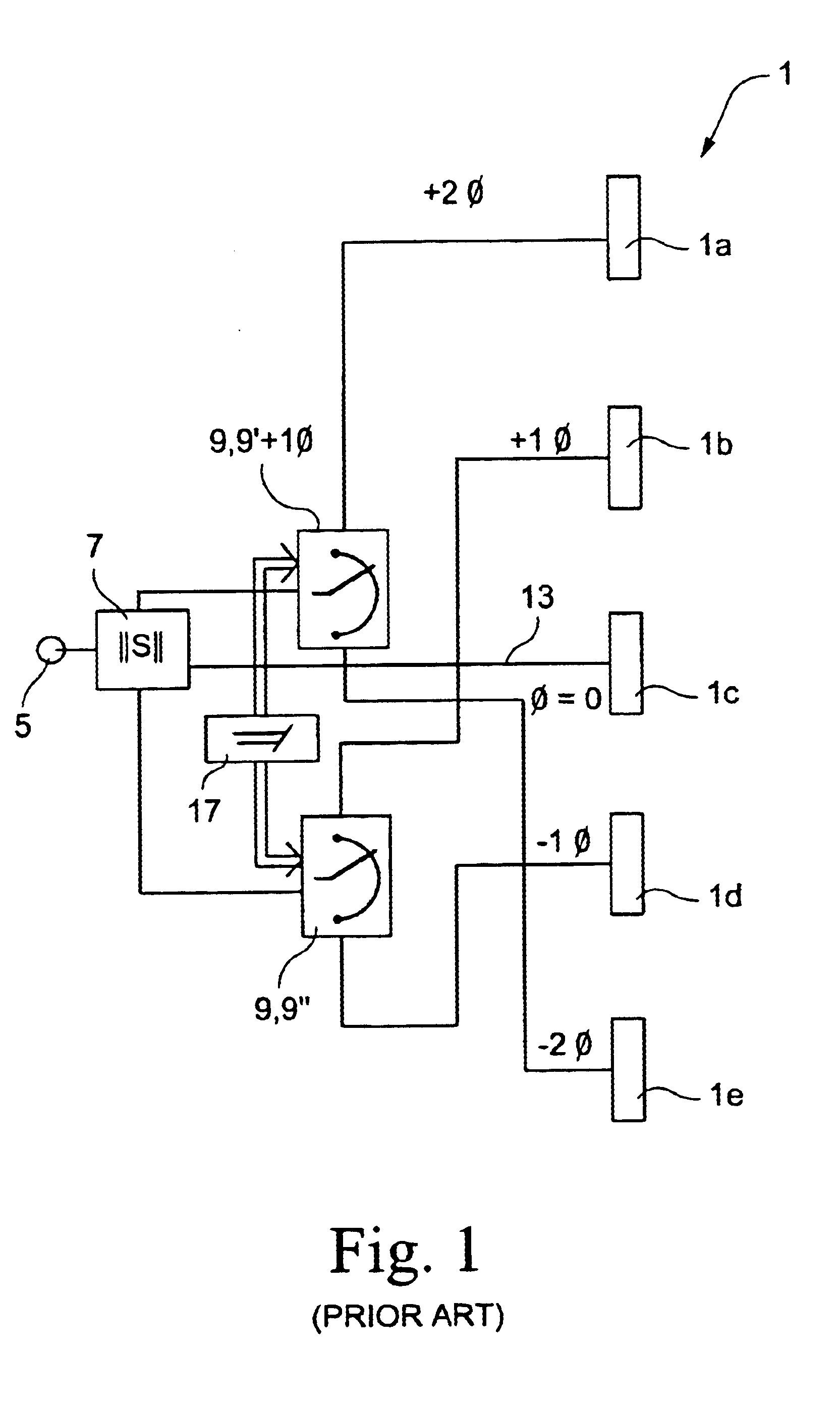
The feed line 13 passes from the feed input 5 to a center ta...


PUM


Abstract

An improved radio-frequency phase shift assembly includes at least one further stripline section arranged concentrically with respect to a first stripline section. Further connection lines are provided, via which an electrical connection is produced at least indirectly from the feed line to the respective tapping section associated with a stripline section. Two different pairs of antenna radiating elements can be driven with different phase angles (Φ) at mutually offset tapping points on the at least two stripline sections. The plurality of connection lines are mechanically connected to one another.

Description

FIELDThe invention relates to a radio-frequency phase shift assembly.BACKGROUND AND SUMMARYPhase shifters are used, for example, for trimming the delay time of microwave signals in passive or active networks. As a known principle, the delay time of a line is used to trim the phase angle of a signal and, in consequence, a variable phase angle means that the lines have different electrically effective lengths.For applications in antennas with an electrically adjustable notch in the polar diagram, the signals have different delay times to the individual radiating elements, for example dipoles. The difference in the delay times between two adjacent radiating elements is approximately the same for a specific notch angle in an array of radiating elements arranged vertically one above the other. This delay time difference is also increased for larger notch angles. If the phase angles of the individual radiating elements are varied by means of phase shift assemblies, then this is an antenna...

Claims


Application Information

Patent Timeline
IPC IPC(8): H01P1/18H01Q3/26
CPCH01Q3/32H01P1/184H01Q19/108H01Q21/08H01P1/18
Inventor GOTTL, MAXIMILIANGABRIEL, ROLANDMARKOF, MATHIAS
Owner TELEFON AB LM ERICSSON (PUBL)
Why Eureka
Try Eureka