
Devices for locating/keeping track of objects, animals or persons

a technology for keeping track of objects and animals, applied in the field of devices for locating or keeping track of objects, animals or people, can solve the problems of inconvenient use, typically inability to activate hands-free devices,

Inactive Publication Date: 2005-02-01
CALHOUN RICKY R +1
View PDF21 Cites 41 Cited by
  • Summary
  • Abstract
  • Description
  • Claims
  • Application Information

AI Technical Summary

Benefits of technology

The present invention relates generally to digital locating devices, and more specifically, to devices which are able to make hands-free preset calls or alerts reminding a user of the location of an object, person or animal or enabling the user to keep track the location of the object, person or animal at preset times.
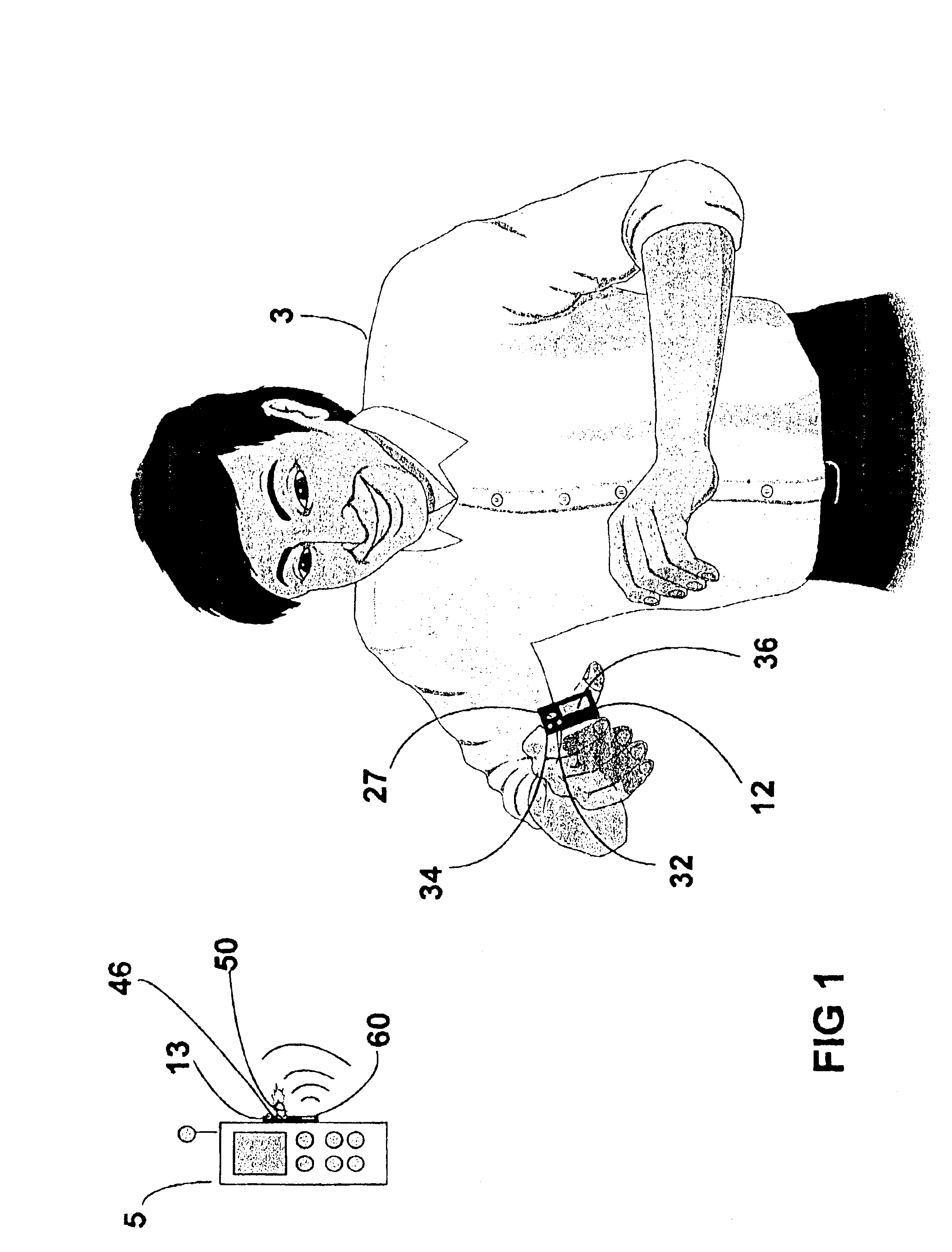
A device for enabling a user to locate an object, person or animal or for reminding the user of the location of an object, person or animal is disclosed by the present invention. The device includes a non-transmitter / receiver embodiment that can be used as a reminder or aid in locating or verifying the location of the object, person or animal. It offers simplicity in structure and use. The non-transmitter / receiver embodiment gives preset “alerts” at desired times by an on-board internal digital electronic clock and microprocessor, by several alerting means (visual and / or audible and / or vibratory). The audible alerting means may be audio messages or music, for example. The visual alerting means may be a flashing display, for example. The alert mode may include a set button to reset or terminate the alert mode, and the alerting means may be activated according to preset timed intervals such as every fifteen seconds, for example. The device includes another embodiment which provides a remote receiver and transmitter. The transmitter includes an on-board digital electronic clock and microprocessor which provides transmittable preset “calls” or activation signals to the receiver at desired preset times, and may include an on-command button for on-command “calls” or activation signals to the receiver. The receiver uses any, some or all of a variety of alerting means such as visual, audible, vibratory, buzzers, audio messages, or music, and / or visual means such as a flashing display. As with the first embodiment, the alert mode may include a set button to reset or terminate the alert mode, and the alerting means may be activated according to preset timed intervals such as every fifteen seconds, for example. Yet a third embodiment includes a transmitter and a receiver housed together in the same casing or housing, with transmittable preset “calls” or activation signals made from the transmitter to the receiver via the transmitter's on-board internal digital electronic clock and microprocessor to make “calls” or activation signals to the on-board receiver or to a remote receiver at preset desired times. The transmitter may further include an “on command” button which may be activated manually by the user to transmit the activation signal from the transmitter to the on-board receiver or remote receiver. The on-board or remote receiver uses any, some or all of a variety of alerting means such as visual, audible, vibratory, buzzers, audio messages, or music, and / or visual means such as a flashing display. As with the first two embodiments, the alert mode may include a set button to reset or terminate the alert mode, and the alerting means may be activated according to preset timed intervals such as every fifteen seconds, for example.

Problems solved by technology

These devices are typically incapable of hands-free activation, and while the devices may be suitable for the particular purposes for which they were designed, they are not suitable for the purposes of the present invention.

Method used


Image

  • Devices for locating/keeping track of objects, animals or persons
  • Devices for locating/keeping track of objects, animals or persons
  • Devices for locating/keeping track of objects, animals or persons

Examples


Embodiment Construction

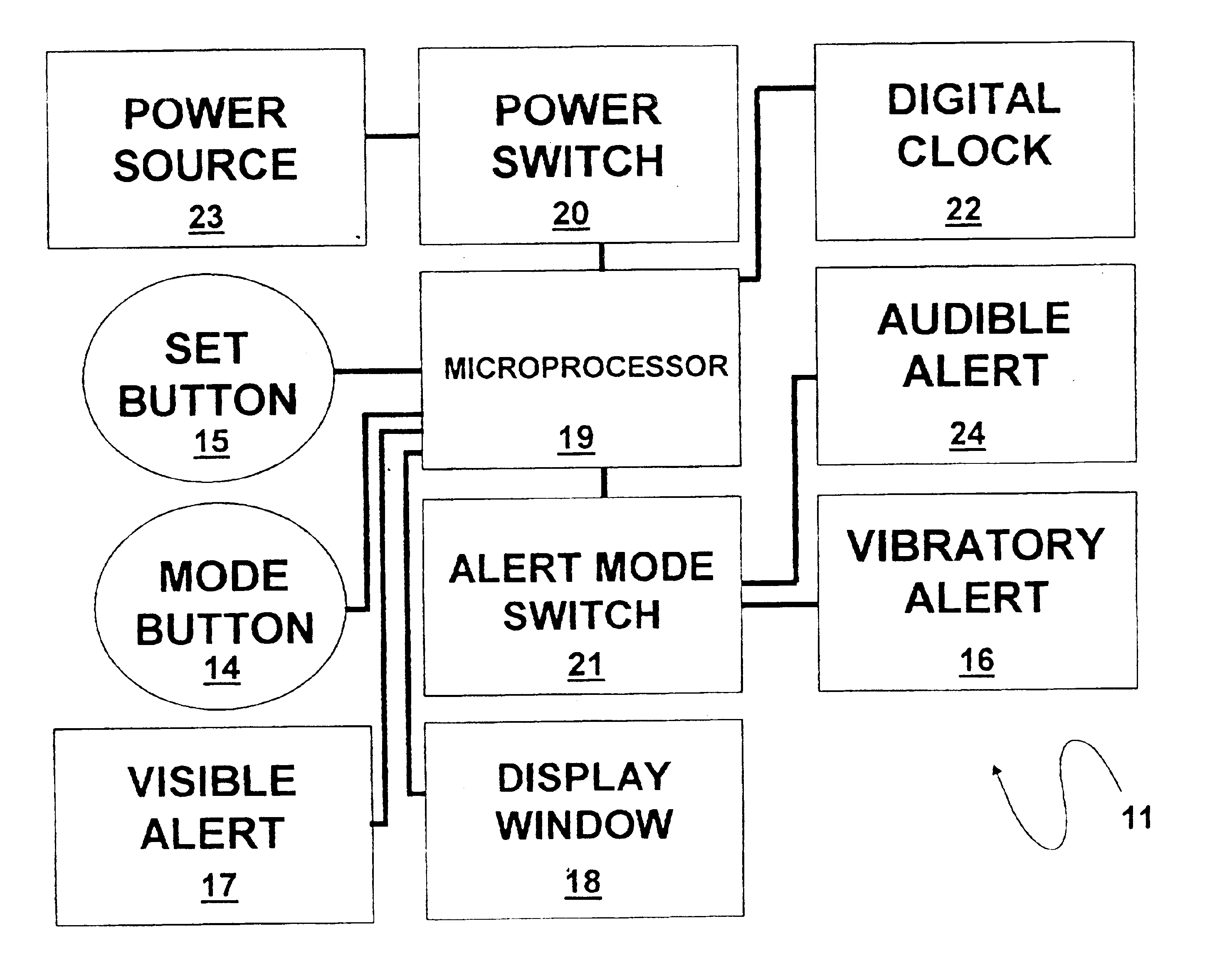
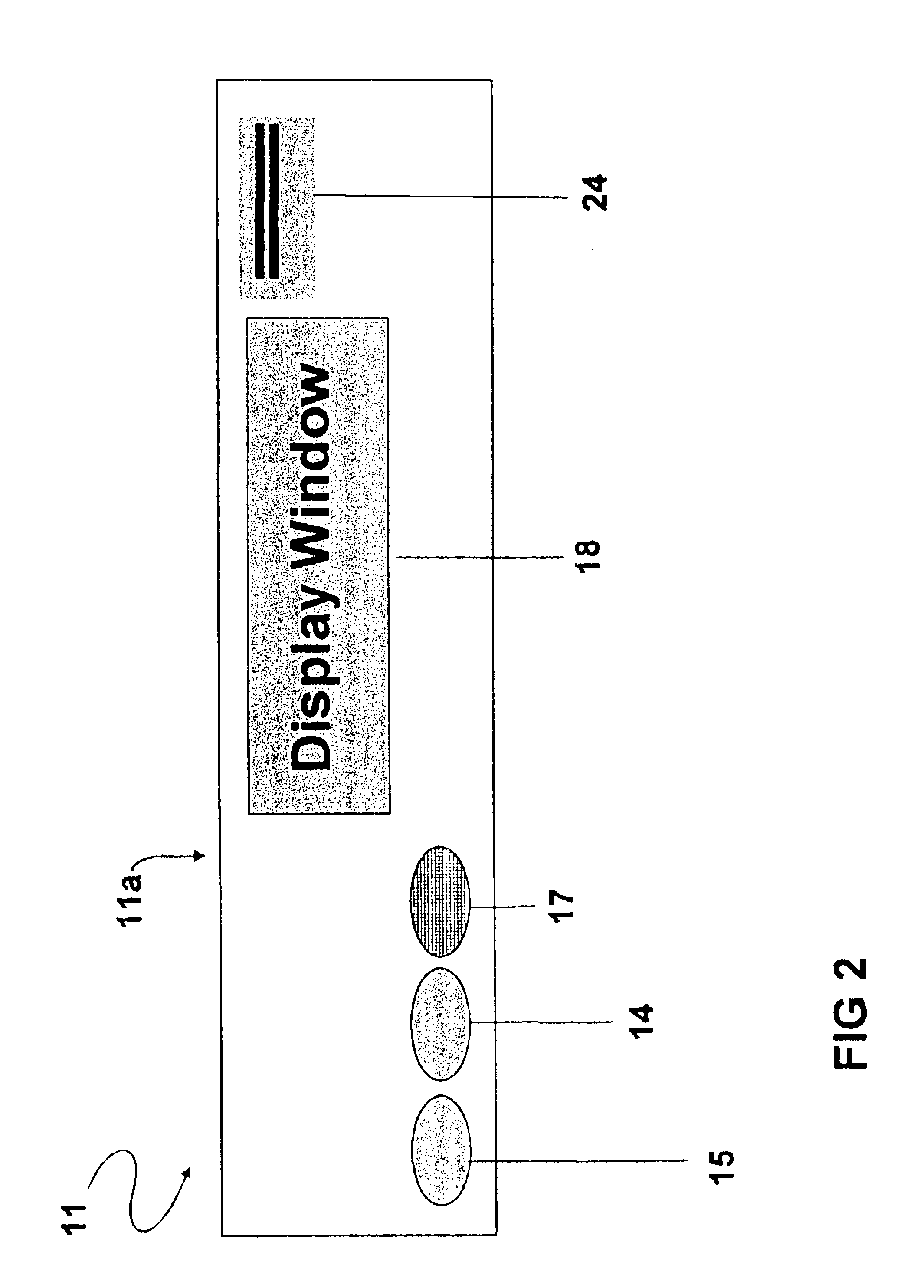
Turning now descriptively to the drawings, in which similar reference characters denote similar elements throughout the several views, FIGS. 2-4 illustrate a non-transmitter / receiver embodiment of the devices of the present invention. The non-transmitter / receiver embodiment of the devices is generally indicated by reference numeral 11. As shown in FIGS. 2 and 3, the device 11 typically includes a housing 11a which houses or supports the various operational elements of the device 11, which operational elements will be hereinafter described with respect to FIG. 4. As shown in FIG. 4, the device 11 includes a microprocessor 19, to which is operably connected a power source 23, such as a battery, through a power switch 20 which is used to selectively supply electrical power to the microprocessor 19 and turn the device 11 on and off, as hereinafter further described. A display window 18, operably connected to the microprocessor 19, is provided on a face of the housing 11a, as shown in FI...


PUM


Abstract

Devices for enabling a user to locate an object, animal or person or reminding the user of the location of an object, animal or person. In a non-transmitter / receiver embodiment, the device includes at least one alert mechanism which is connected to a digital clock or other timer and microprocessor which times transmission of alert signals emitted from the alert mechanism or mechanisms. The operational components of the device may be contained in a housing which is attached to the object, animal or person to be located. In a remote transmitter / receiver embodiment, the device includes a transmitter which transmits activation signals at preset times to activate an alert feature of a paired remote receiver which is provided on the object, animal or person to be located or tracked. The transmitter may include an on-command button for manual transmission of the activation signals to the receiver. The receiver may have a visible alert mode in combination with a selected audible or vibratory alert mode. In an on-board transmitter / receiver embodiment, the device includes a transmitter which is housed together with a receiver in a single unit. In that case, the transmitter of one unit can transmit preset timed activation signals to the receiver of a different unit which is placed on the object, animal or person. Alternatively, the transmitter of one unit can transmit preset timed activation signals to the receiver of the same unit placed on the object, animal or person.

Description

FIELD OF THE INVENTIONThe present invention relates to devices for locating or keeping track of objects, animals or persons. More particularly, the present invention relates to devices which emit timed alarm signals to assist a user in locating or keeping track of the location of various objects such as cell phones, pagers, laptop computers and keys; animals such as pets; or persons such as toddlers or small children, for example.BACKGROUND OF THE INVENTIONNumerous types of locating devices are known in the art for locating or keeping track of objects, persons or animals. These devices typically include a receiver which is positioned on the object, person or animal while a transmitter for typically manual activation by the receiver is held or worn by a searcher or operator. Such devices require the operator to manually transmit an activation signal from the transmitter to the paired receiver, which emits an alarm or other signal. These devices are typically incapable of hands-free a...

Claims


Application Information

Patent Timeline
IPC IPC(8): G04G13/00G08B21/00G04G15/00G04G13/02G08B7/00G08B7/06G08B21/24
CPCG04G13/021G08B21/24G08B7/06G04G15/00
Inventor CALHOUN, RICKY R.PETTERWAY, NATHANIEL
Owner CALHOUN RICKY R
Learn More