Video signal processing apparatus

a video signal and processing apparatus technology, applied in the field of video signal processing apparatus, can solve the problems of unable to apply the servo feedback method in the above-described conventional tbc system, the drawing of freezing images or generating block noise,

Inactive Publication Date: 2005-02-01
MAXELL HLDG LTD
View PDF2 Cites 13 Cited by
  • Summary
  • Abstract
  • Description
  • Claims
  • Application Information

AI Technical Summary

Benefits of technology

[0009]In order to resolve this, there is conceivable a method of suppressing jitter provided to the nonstandard signal by providing the above-described time axis correcting circuit TBC at a prestage of the image compression circuit. However, in the case in which there is a deviation in an average period of the input signal, the method of servo feedback in the above-described conventional TBC system can no more be applied. Because although the servo feedback is effective in the case in which the period of the reproduced signal inputted by controlling the rotating cylinder in reproduction is adjusted, as the period of the input signal in recording operation, explaining by taking an example of TV broadcast, this is a period determined by the facility of the broadcast station and it is impossible to change the period by applying the above-described method of servo feedback with regard thereto.
[0010]It is an object of the present invention to resolve the above-described problem of the conventional technology and to provide a video signal processing apparatus having a time axis correcting function for processing an input signal to an image compression circuit in a mode proximate to a standard signal and preferably capable of processing also a case of inputting a non-interlace signal or a nonstandard signal a field length of which differs from standard.
[0011]In order to resolve the above-described problem, according to an aspect of the present invention, there is provided a video signal processing apparatus comprising a memory to which an inputted first video signal is written, a compression circuit for subjecting a second video signal read from the memory to data compression, and an expansion circuit for generating a third video signal by subjecting the compressed signal to data expansion, further comprising a synchronizing signal separator for separating first synchronization information from the first video signal, writing and reading control circuits for controlling writing and reading to and from the memory, a changeover switch for selecting and outputting either one of the first and the second video signals or the third video signal, and a switch control circuit for controlling to select the changeover switch based on the first synchronization information.
[0012]According to another aspect of the present invention, there is provided the video signal processing apparatus, further comprising a field discriminator for discriminating whether the first video signal is an interlace signal or a noninterlace signal from the first synchronization information, wherein the switch control circuit controls to switch the changeover switch based on a result of discrimination of the field discriminator. According to another aspect of the present invention, there is provided the video signal processing apparatus further comprising a field length detector for detecting a field length from the first synchronization information, wherein the switch control circuit controls to switch the changeover switch based on a value of the field length Tf1.
[0013]Further, according to another aspect of the present invention, there is provided a video signal processing apparatus for writing an inputted first video signal to a memory and reading the first video signal from the memory as a second video signal, the video signal processing apparatus comprising a synchronizing signal separator for separating first synchronization information from the first video signal, a write control circuit for controlling writing to the memory based on the first synchronization information, a synchronizing signal generator for generating second synchronization information, and a read control circuit for controlling reading from the memory based on the second synchronization information, wherein the synchronizing signal generator generates the second synchronization information having a front edge of a vertical synchronization waveform at a position delayed from a front edge of a vertical synchronization waveform included in the first synchronization information by a predetermined delay time Td.

Problems solved by technology

Therefore, when a nonstandard signal is inputted, there poses a problem of causing a drawback of freezing image or generating block noise or the like.
However, in the case in which there is a deviation in an average period of the input signal, the method of servo feedback in the above-described conventional TBC system can no more be applied.

Method used


Image

  • Video signal processing apparatus
  • Video signal processing apparatus
  • Video signal processing apparatus

Examples


Embodiment Construction

n example of a head locus in special reproducing operation in a helical scan VTR;

[0020]FIG. 4 is a diagram showing an example of a timing of generating a reset pulse in FIG. 1;

[0021]FIG. 5 is a diagram showing an example of a method of generating the reset pulse in FIG. 1; and

[0022]FIGS. 6a and 6b are views showing a correspondence between a track pattern and a head constitution in the helical scan VTR.

DETAILED DESCRIPTION OF THE INVENTION

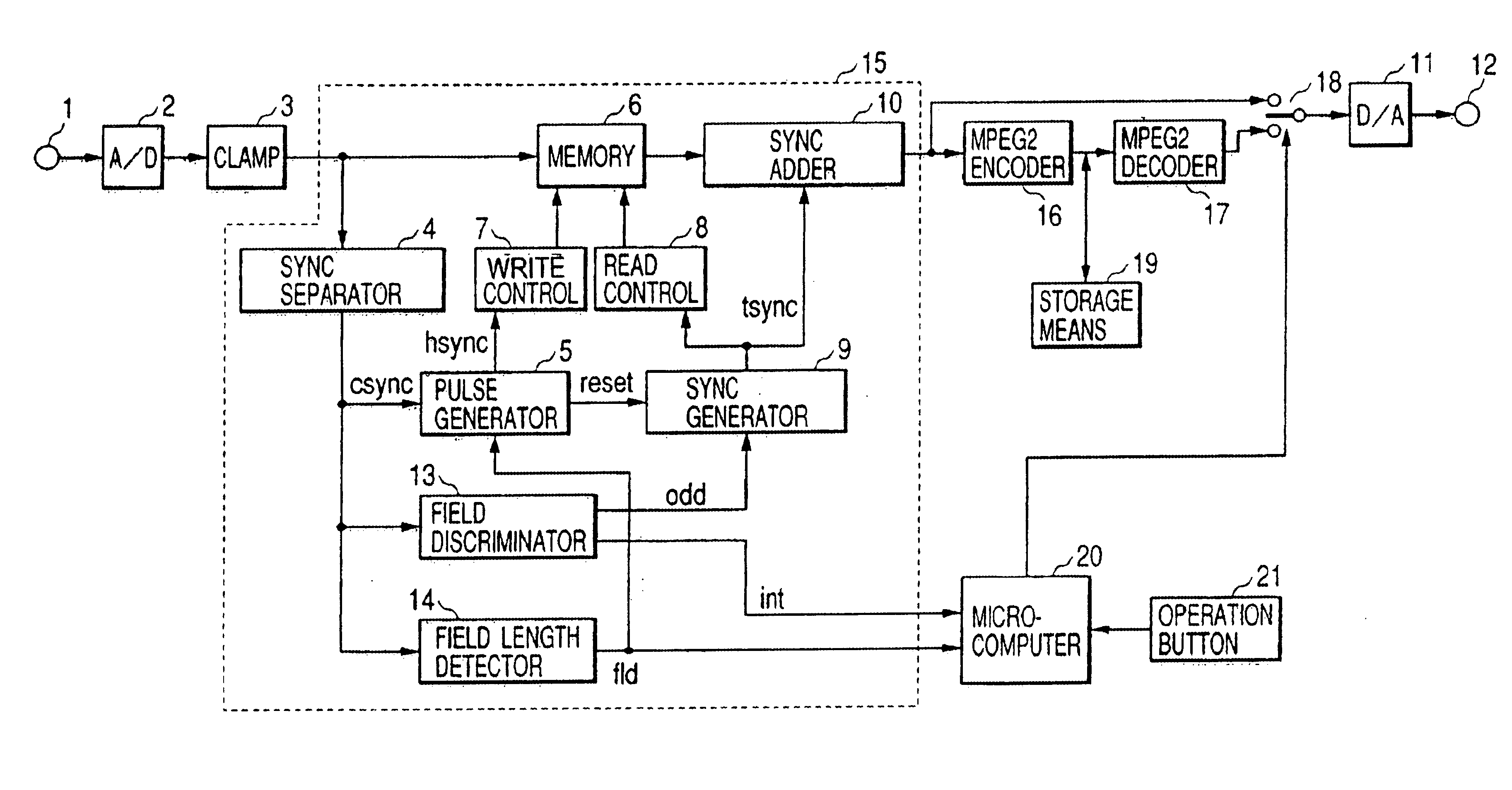
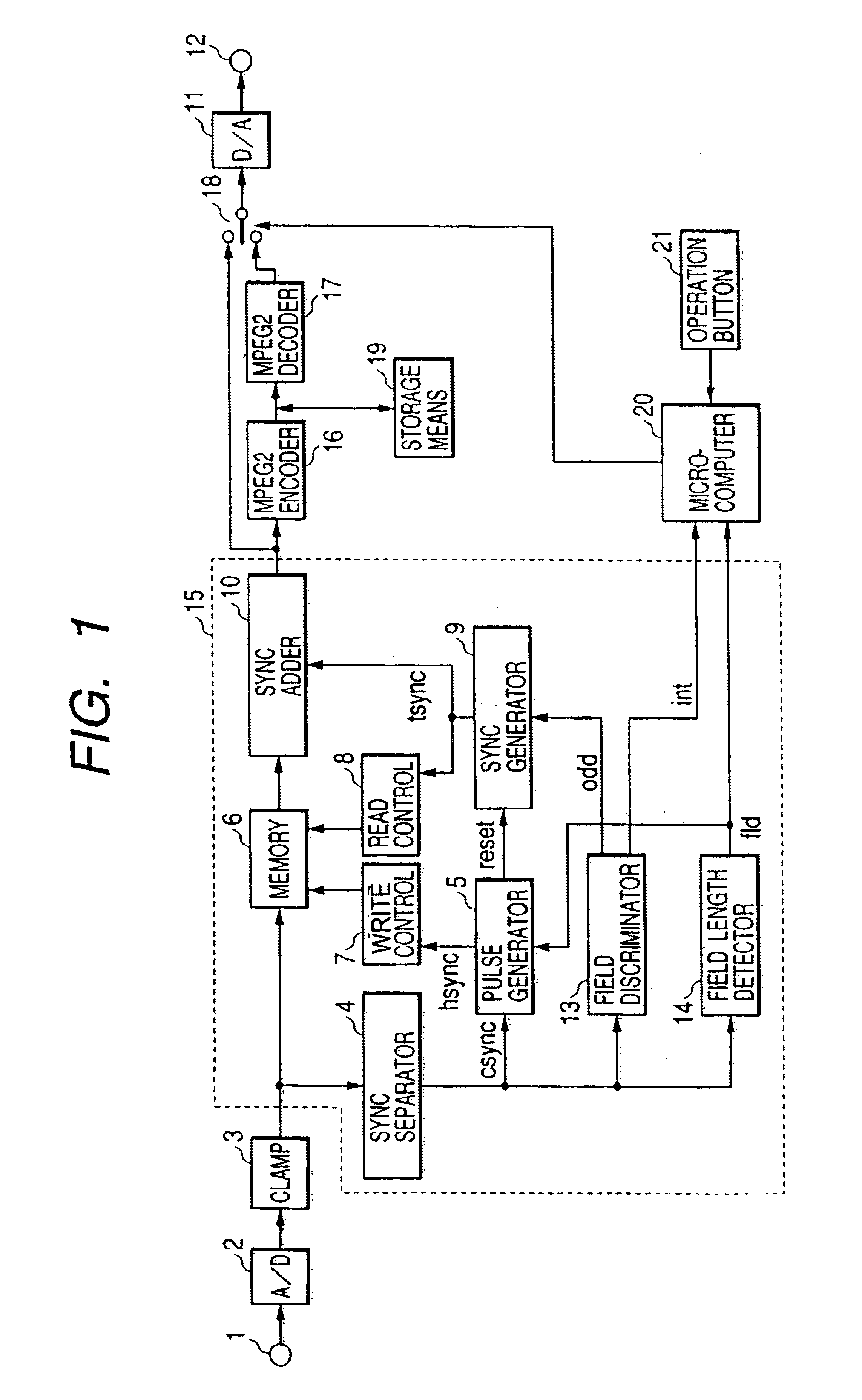
[0023]An explanation will be given of an embodiment of a video signal processing apparatus according to the present invention as follows. FIG. 1 shows a block diagram of a video signal processing apparatus according to the present invention. A video signal inputted from the terminal 1 is subjected to digital conversion by the A / D converter 2, subjected to the clamp processing by the clamp circuit 3 and is inputted to the synchronizing signal separator 4 and the memory 6. At the synchronizing signal separator 4, a synchronizing signal of the input s...


PUM


Abstract

The present invention relates to a video signal processing apparatus for outputting an inputted video signal after subjecting the video signal to time axis correction, particularly to a video signal processing apparatus preferable in the case of subjecting the video signal to image compression. In the case in which a nonstandard signal is inputted to an image compression circuit of an MPEG2 encoder or the like, a drawback of freezing image or generating block noise or the like is resolved. A time axis correcting circuit stores an input signal to a memory and reads the input signal at a timing delayed from V synchronization of the input signal by a predetermined time period. For that purpose, a read synchronizing signal generator is reset at respective input field. A reset position is set to a position preceding the read V synchronization position by 3H through 10H. It is detected whether the input signal is a non-interlace signal or a field length thereof is deviated from a standard value and in these cases, odd/even order or synchronization timing of a synchronizing signal is corrected. Further, when the input signal is a nonstandard signal, the input signal is outputted without passing through the image compression circuit by a changeover switch.

Description

BACKGROUND OF THE INVENTION[0002]The present invention relates to a video signal processing apparatus for outputting an inputted video signal after subjecting the video signal to time axis correction, particularly to a video signal processing apparatus preferable when the video signal is subjected to image compression.[0003]In a reproduced signal processing of conventional VTR for household use, there is used a time axis correcting circuit or a time base corrector (hereinafter, abbreviated as TBC) for correcting a variation in an input signal with respect to a time axis. TBC corrects a time axis error by executing writing to a memory based on a write control signal having a time axis variation substantially the same as the time axis variation in the input signal and executing reading from the memory based on a read control signal substantially in synchronism with a period of a synchronizing signal of a standard signal. The technology is described, for example, in “Home video technol...

Claims


Application Information

Patent Timeline
Patent Type & Authority Patents(United States)
IPC IPC(8): H04N9/89H04N9/896H04N9/804H04N5/7824H04N5/783H04N5/7826H04N5/765H04N5/95H04N5/956
CPCH04N9/896H04N5/78263H04N9/8042H04N5/783
Inventor MORO, EIJISODEYAMA, KENHORI, HIROYUKIWATANABE, KATSUYUKITABATA, AKIFUMI
Owner MAXELL HLDG LTD
Why Eureka
Try Eureka