Construction machinery

a construction machinery and construction technology, applied in the field of construction machinery, can solve the problems of increasing energy loss, low pump efficiency, and large energy loss, and achieve the effect of raising and lowering

Inactive Publication Date: 2005-02-08
KOBELCO CONSTR MASCH CO LTD
View PDF18 Cites 58 Cited by
  • Summary
  • Abstract
  • Description
  • Claims
  • Application Information

AI Technical Summary

Benefits of technology

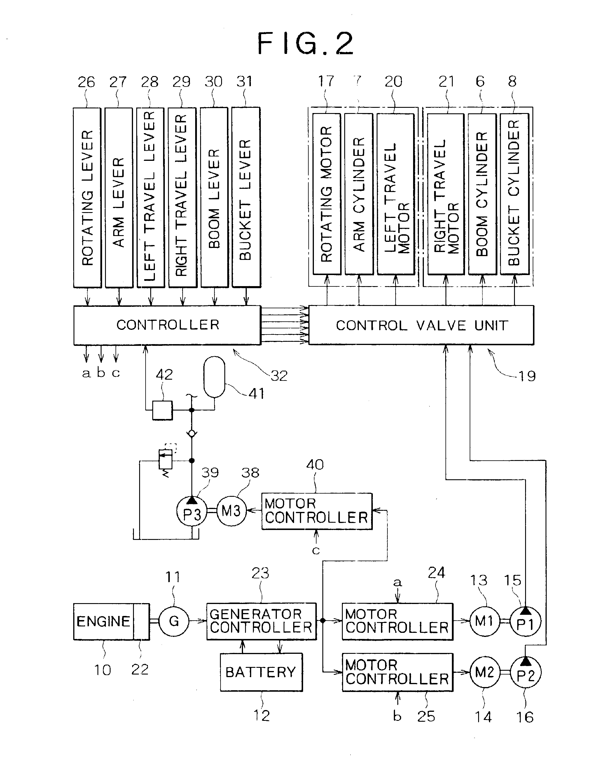
In another aspect of the present invention there is provided a construction machine comprising a plurality of hydraulic actuators, a hydraulic pump for operating the hydraulic actuators, an electric motor for activating the hydraulic pumps control valves disposed between the hydraulic pump and the hydraulic actuators to control the supply and discharge of pressure oil to and from the hydraulic actuators, operating means which are operated from the exterior and which issue operation commands to the control valves, and a controller which in accordance with operations of the operating means controls an operation stroke of each of the control valves and the number of revolutions of the electric motor.
In a further aspect of the present invention there is provided a construction machine comprising a plurality of hydraulic actuators, a plurality of hydraulic pumps which operate the hydraulic actuators separately, a plurality of electric motors which activate the hydraulic pumps separately, control valves disposed between the hydraulic pumps and the hydraulic actuators to control the supply and discharge of pressure oil to and from the hydraulic actuators, operating means which are operated from the exterior and which issue operation commands to the control valves, and a controller which in accordance with operations of the operating means controls an operation stroke of each of the control valves and the number of re...

Problems solved by technology

With this construction, not only there arises a great loss of energy but also there arise problems related to environmental pollution such as the generation of noise and exhaust gas.
Thus, the pump efficiency is low and the loss of energy increases because a surplus flow in each pump is discarded to the tank through a valve.
In this case, according to the prior art, since both boom cylinder and bucket cylinder are actuated by the same pump, it is required that the pressure of oil discharged from the pump, when increased up to the pressure of the bucket cylinder, be lowered with a control valve and then fed to the boom cylinder, thus causing a pressure (energy) loss.2. Since there is adopted a construction wherein all of the boom, arm and bucket cylinders are controlled their operating speeds by a control valve ...

Method used


Image

  • Construction machinery
  • Construction machinery
  • Construction machinery

Examples


second embodiment (see fig.7)

Second Embodiment (See FIG. 7)

In the following second to fourth embodiments reference will be made to only different points from the first embodiment.

In the construction of the first embodiment bleed-off passages are provided in the control valves 33˜36 respectively, while in this second embodiment bleed-off passages are not provided in the control valves 33˜36, but a bleed-off valve 43 as an independent bleed-off means shared by the control valves 33˜36 is provided in a pump discharge circuit. In accordance with a command signal d, which is provided from the controller 32 on the basis of lever operation, the bleed-off valve 43 operates and exhibits the same valve characteristic as in the first embodiment.

According to this construction, the control valves 33˜36 become compact and it is possible to compensate for the decrease of a device mounting space caused by an increase of device types which results from the tendency to a hybrid configuration.

third embodiment (see figs.8 and 9)

Third Embodiment (See FIGS. 8 and 9)

In this third embodiment, bleed-off means is provided neither in the control valves 33˜36 nor in the exterior, and the number of revolutions of each electric motor (pump discharge rate) is controlled in accordance with lever operation quantity.

That is, as shown in FIG. 9, when the levers are in their neutral positions, the number of revolutions of the electric motor is zero, and at point A the number of revolutions of the electric motor begins to rise, then increases continuously as the lever operation quantities increase.

The strokes of the control valves are controlled in accordance with lever operation quantities, and at point A meter-in openings being to open (or are open slightly) and oil begins to flow in the actuators.

By so doing, there is no bleed-off portion and no flow that is throttled and discarded as bleed-off flow, thus resulting in a further advantage being obtained in point of energy saving.

The lever operation quantity vs. electric ...

fourth embodiment (see figs.10 and 11)

Fourth Embodiment (See FIGS. 10 and 11)

In this fourth embodiment there is used an electric motor 44 (fourth electric motor, indicated at M4 in FIG. 10) in place of a hydraulic motor as the rotating actuator and there is adopted a construction wherein:(a) the fourth electric motor 44 is controlled through an electric motor controller 45 in accordance with a number-of-revolutions command signal e which is provided from the controller 32 on the basis of lever operation, and(b) the electric motor 44 is allowed to operate as a generator during rotation braking.

The above control (a) may be a number-of-revolutions control or may be a torque control through current control, or even may be a composite control of both speed and torque, and is thus suitable for controlling a rotating operation of a hydraulic excavator which is large in inertia.

By the above control (b) there acts a regenerative brake and electric power obtained by the regenerative action is stored in the battery 12 or is utiliz...


PUM


Abstract

First and second hydraulic pumps each adapted to operate plural actuators are activated by separate electric motors respectively. In accordance with signals provided from a controller on the basis of operations of levers, the number of revolutions of the electric motor and that of the electric motor are controlled each independently and simultaneously to control the discharge rates of both hydraulic pumps.

Description

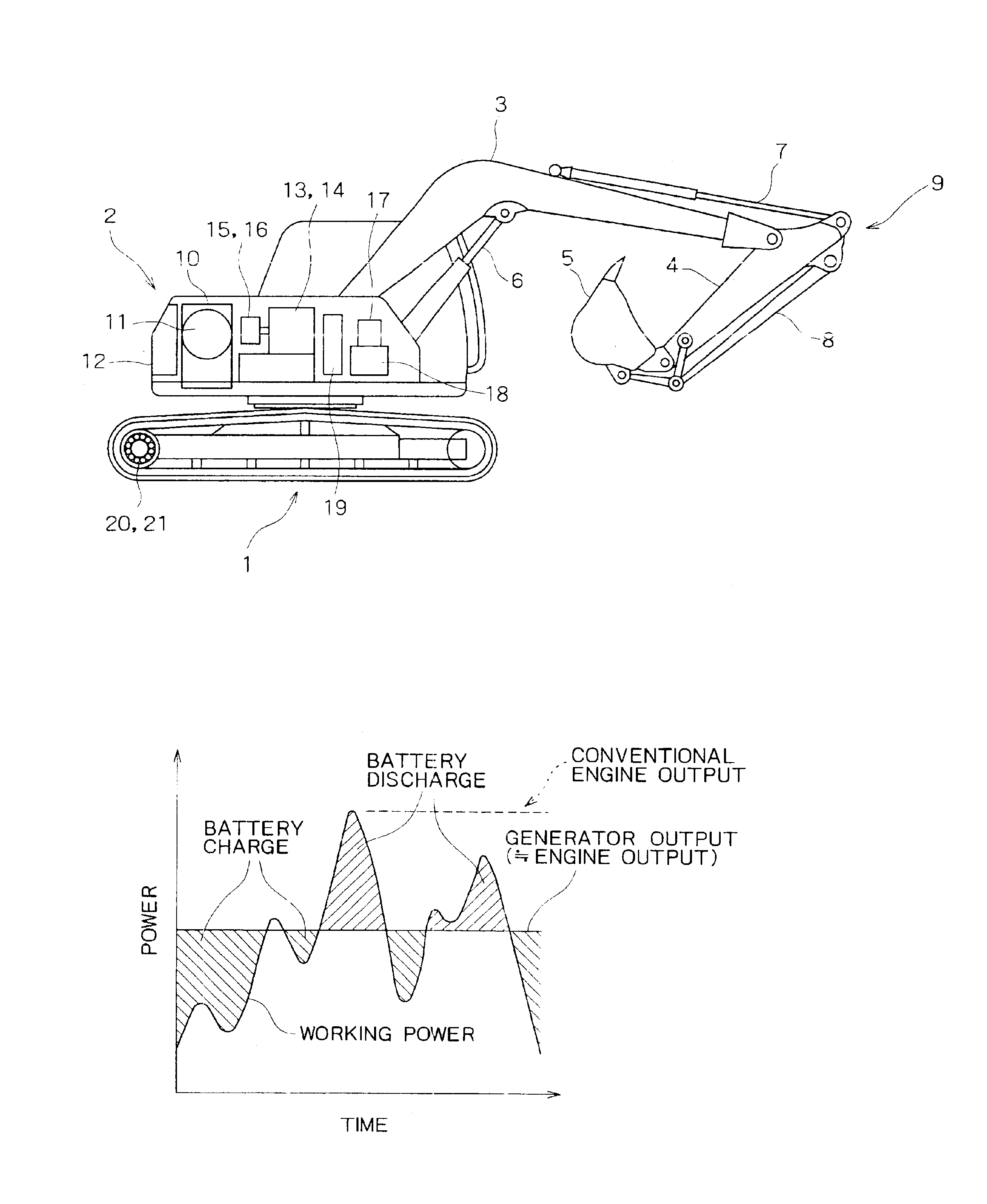
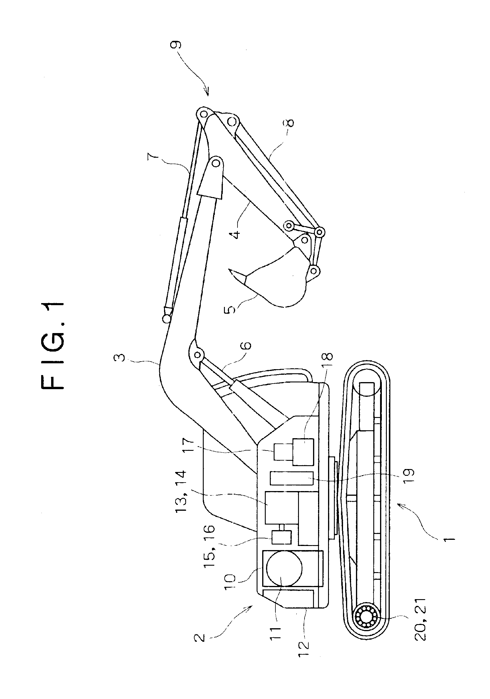
FIELD OF ARTThe present invention relates to a construction machine (e.g., a hydraulic excavator or a crane) wherein hydraulic pumps are activated by electric motors to operate hydraulic actuators.BACKGROUND ARTThe prior art will be described below with respect to a hydraulic excavator for example.According to the construction of a conventional hydraulic excavator, an upper rotating body is mounted rotatably on a lower traveling body, an excavating attachment comprising a boom, an arm, and a bucket is attached to the upper rotating body, and hydraulic oil discharged from pumps is fed to hydraulic actuators to effect booming, arming, bucketing, traveling, and rotating operations.According to the construction of the conventional hydraulic excavator, however, the pumps are activated by an engine and pressure oil discharged from the pumps is fed to hydraulic actuators through control valves. Thus, a surplus flow in each pump is throttled and discarded into a tank through a control valve...

Claims


Application Information

Patent Timeline
IPC IPC(8): E02F9/20F15B11/16F15B11/00F15B21/08F15B21/00E02F9/22
CPCE02F9/2025E02F9/2292F15B11/165F15B11/167F15B21/087E02F9/2075F15B2211/7135F15B2211/205F15B2211/20515F15B2211/20523F15B2211/20561F15B2211/20584F15B2211/212F15B2211/30505F15B2211/3051F15B2211/30525F15B2211/3056F15B2211/3111F15B2211/3127F15B2211/3133F15B2211/31576F15B2211/327F15B2211/329F15B2211/355F15B2211/45F15B2211/455F15B2211/46F15B2211/50518F15B2211/5151F15B2211/63F15B2211/6316F15B2211/6355F15B2211/6658F15B2211/67E02F9/2095E02F9/2228E02F9/2012E02F9/20
Inventor YOSHIMATSU, HIDEAKI
Owner KOBELCO CONSTR MASCH CO LTD
Why Eureka
Try Eureka