Device for converting a linear movement into a rotary movement

a technology of rotary movement and linear movement, which is applied in the direction of connecting rods, bearings, belts/chains/gearrings, etc., can solve the problem of difficult to provide a favourable transmission of force from the piston to the crankshaft, and achieve the effect of favourable transmission of for

Inactive Publication Date: 2005-02-08
ERIKSSON SVEN KENNETH
View PDF10 Cites 5 Cited by
  • Summary
  • Abstract
  • Description
  • Claims
  • Application Information

AI Technical Summary

Benefits of technology

[0011]However, it should be pointed out that the arguments above are not stated with the ambition to completely describe the underlying relationships or mechanisms, which give rise to the advantages of the device according to the invention. Instead the description above may be seen as an outline of a theory which possibly may explain why the device according to the invention has better performance than such corresponding conventional devices. However, the advantages have unambiguously been proved by carrying out experiment in which the invention has been applied in an Otto engine having four cylinders. The concrete advantages of the invention applied in a combustion engine is that the engine may provide a higher torque on the crankshaft, which in its turn means that the engine may supply a certain output at a lower rotation speed, which in its turn would lead to lower fuel consumption. Furthermore, the engine according to the invention is less disposed to knock, i.e. there is a smaller risk that non-combusted fuel-air mixture will self-ignite in an undesired way. It has been established that by the engine according to the invention it is possible to compress the fuel-air mixture up to higher pressures than what is possible in conventional Otto engines, in some cases up to a pressure exceeding 15 bar, without any knocking (self-ignition) appearing. Furthermore, measures of the exhaust of the engine by a lambda probe indicate that a more complete combustion of the fuel is obtained. It should also be mentioned that the engine according to the invention needs less cooling than normally and this indicates that a greater part of the energy of the fuel is transferred to useful work on the crankshaft and a smaller part is transferred to heat.

Problems solved by technology

A disadvantage of today's combustion engines is the difficulty to provide a favourable transmission of force from the piston to the crankshaft during the phase of the expansion stroke when the combustion gases give rise to the greatest forces on the piston, i.e. shortly after the moment of ignition.

Method used


Image

  • Device for converting a linear movement into a rotary movement
  • Device for converting a linear movement into a rotary movement
  • Device for converting a linear movement into a rotary movement

Examples


Embodiment Construction

ed into a rotation movement of a crankshaft via a connecting rod,

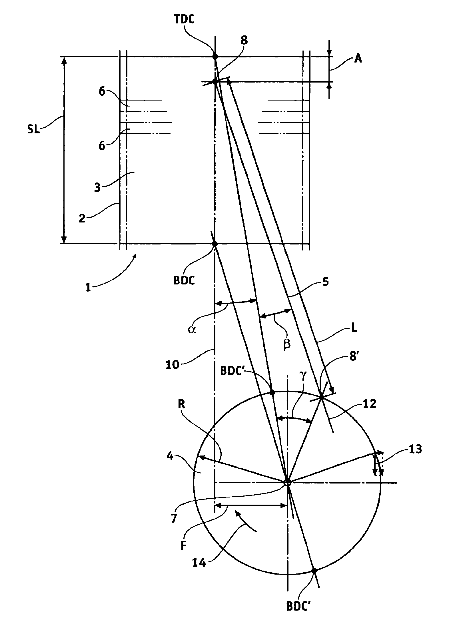
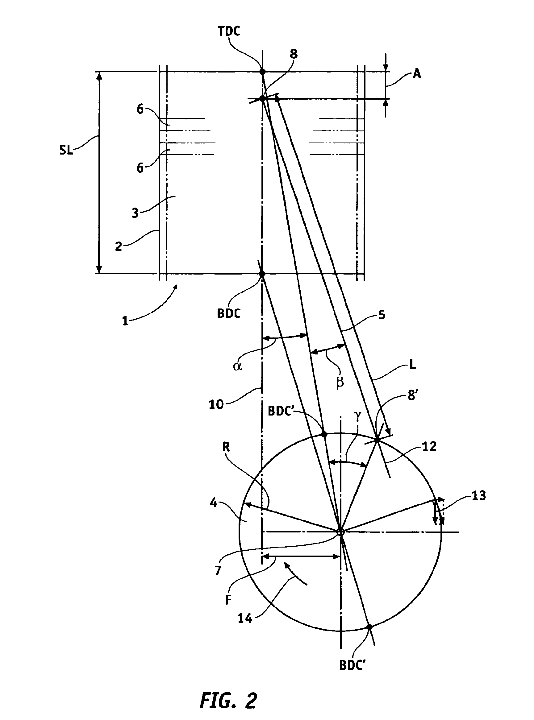
[0020]FIG. 2 is a schematical view in accordance with FIG. 1, the centre rotation of the crankshaft being displaced in relation to the movement line of the piston,

[0021]FIG. 3 is a schematical view in accordance with FIG. 2, the relation between the length of the connecting rod and the stroke length being less than 1.5, and

[0022]FIG. 4 is a table of piston movement in relation to rotation of the crankshaft.

DETAILED DESCRIPTION OF PREFERRED EMBODIMENTS OF THE INVENTION

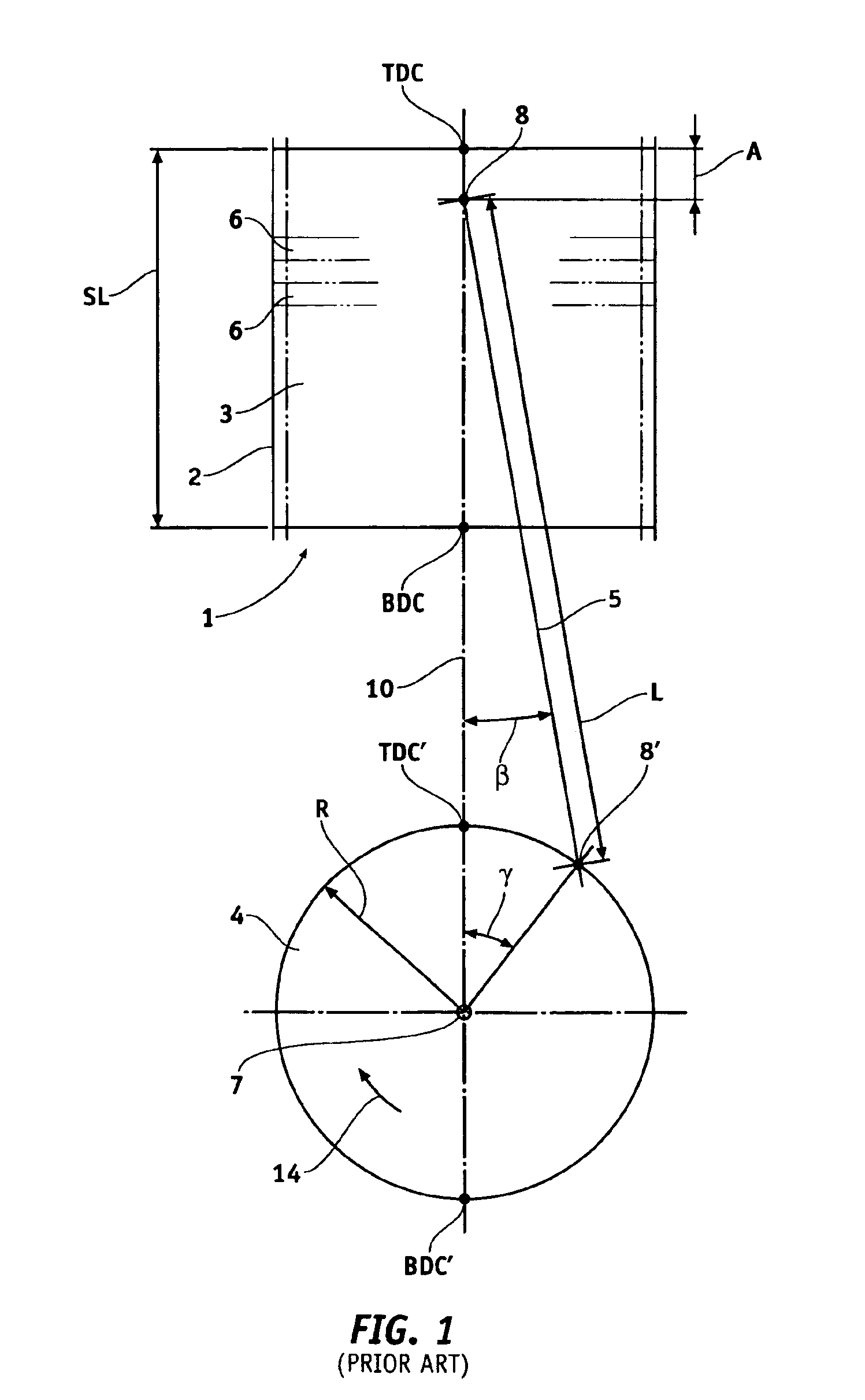
[0023]In FIG. 1 a piston-cylinder mechanism 1 having a cylinder 2 and a piston 3 movably arranged in the cylinder 2 for rectilinear movement, a crankshaft 4 for rotary movement and a connecting rod 5 connecting the piston 3 and the crankshaft 4 are schematically illustrated. The piston 3 which is suitably gas-sealed by piston rings 6 and runs in the cylinder 2 is arranged for repeated movement backwards and forwards between two extreme positions called upp...


PUM


Abstract

A device for converting a rectilinear movement into a rotary movement, comprising at least one piston-cylinder mechanism having a cylinder and a piston moveable arranged in the cylinder for rectilinear movement, a crankshaft for rotary movement, and a connecting rod connecting the piston and the crankshaft, the centre of rotation of the crankshaft being arranged displaced at a distance from the line along which the piston is moveable and that the crankshaft has a direction of rotation so that the part of the crankshaft which in relation to the movement line of the piston is located on the other side of the centre of rotation of the crank shaft, looked at the device in the longitudinal direction of the crankshaft has a movement component which is parallel with the movement line of the piston and directed away from the cylinder.

Description

[0002]This is a continuation of Application No. PCT / SE01 / 00003, filed Jan. 2, 2001.FIELD OF THE INVENTION AND PRIOR ART[0003]The present invention relates to a device for converting a rectilinear movement into a rotary movement, comprising at least one piston-cylinder mechanism having a cylinder and a piston movably arranged in the cylinder for a rectilinear movement, a crankshaft for rotary movement, and a connecting rod connecting the piston and the crankshaft. The invention also relates to the use of such a device in a piston engine having internal combustion.[0004]In the following the invention will be described by means of different examples of embodiments of the device, which may be applied in the engines, such as different types of single and multiple cylinder combustion engines, for converting a rectilinear movement into a rotary movement. In this connection a number of frequently used expressions within the technical field of engines are used. The current expressions are am...

Claims


Application Information

Patent Timeline
Patent Type & Authority Patents(United States)
IPC IPC(8): F01B9/02F01B9/00F02F7/00F16H21/24F16H21/00F02B75/32
CPCF01B9/02F16H21/24F02F7/0019F02B75/32
Inventor NYSTROM, RUNE
Owner ERIKSSON SVEN KENNETH
Why Eureka
Try Eureka